ECODRIVE03 Drive Controllers ECODRIVE03 DKC**.040, DKC**.100, DKC**.200 4-89
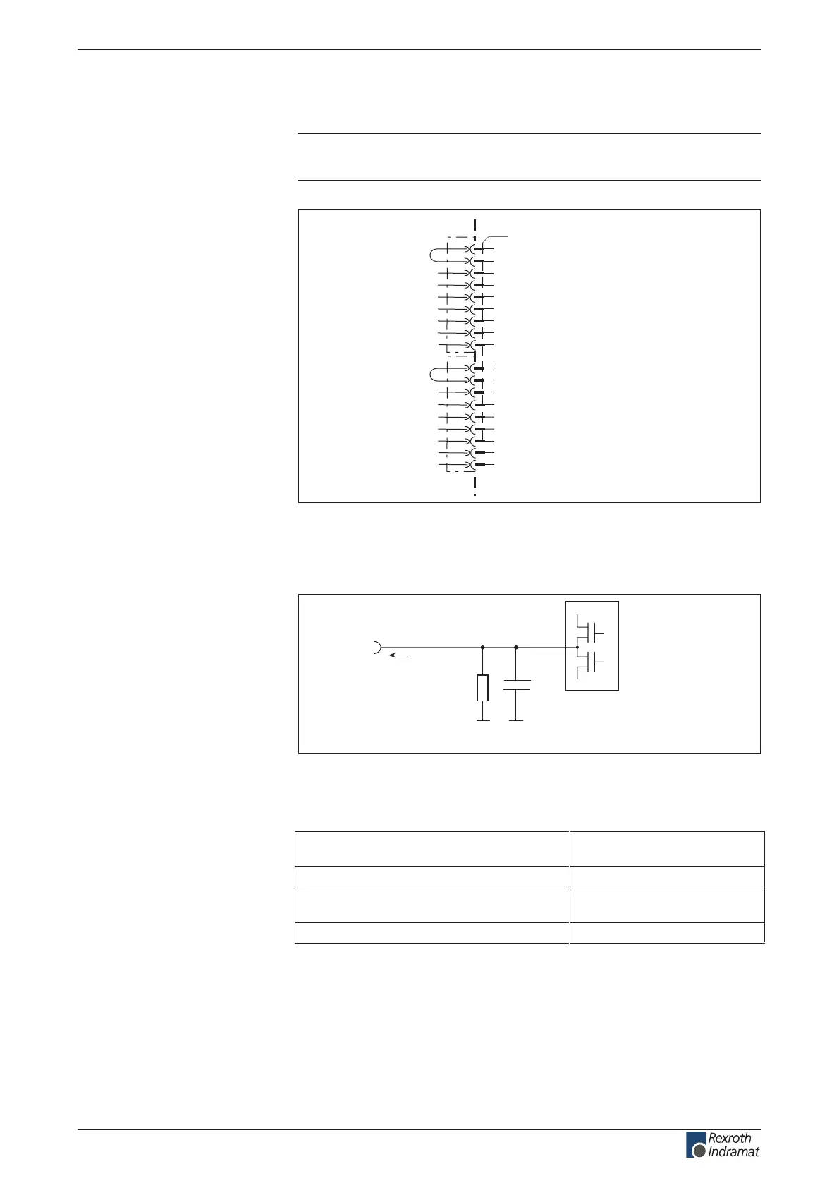
ZKS control supply
Note: Internal DC bus dynamic brake setup (ZKS) not in
DKC**.3-040-7-FW.
AP5284F1.FH7
X11
1
2
3
4
5
6
7
8
10
11
12
13
14
15
ZKS1
+24Vpro
ZKS2
16
18
17
9
0V
device-external device-internal
Fig. 4-141: DC bus dynamic brake control
At delivery: with bridges at: X11.1 to X11.2
X11.10 to X11.11
Ap5184f1.fh7
R1
C1
Q
n
I
out
Schematics
R1: approximately 12 R
C1: 470 µF
Fig. 4-142: Voltage source from X2.1
max. output voltage
(dependent of control voltage an X1.1)
DC (19.2...28.8) – 2 V
A 1.0 CD:tnerruc tuptuo dewolla .xam
retimil tnerruc gnigrahc aivnoitcetorp daolrevo lamrehT
behind X1.1
A 4.2tnerruc tiucric trohs .xam
The connections supported the ZKS inputs.
Connection
+24Vpro and 0V:
Output
+24Vpro:
Loadability of the connection
+24Vpro:
Application
+24Vpro:
customerservice@hyperdynesystems.com | (479) 422-0390

 Loading...