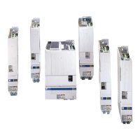
4-90 ECODRIVE03 DKC**.040, DKC**.100, DKC**.200 ECODRIVE03 Drive Controllers
ZKS control input
See page 4-89: "ZKS control supply".
AP5280F1.FH7
ZKS2
ZKS1
C1
R1V1
C2
V2
Schematics
R1: 2k2
V1: 10V
V2: 0.7V
C1: 0.1µF
C2: 0.1µF
Fig. 4-143: Input circuit
Input voltage:
High
Low
min.
15 V
0 V
max.
28.8 V
4 V
trigger delay t
d
due to
contactor drop delay
min.
40 ms
max.
80 ms
mhOk 2 tuobaecnatsiser tupnI
ffeV 05 otnoitalosi laitnetoP
Polarity protected within allowed input voltage range
Fig. 4-144: Inputs
The connections supply the ZKS input and permit potential free control of
DC bus dynamic brake setup via a relay contact.
Mains voltage at X5 DC input DC bus setup
not applied no current active
not applied current not active
applied not current not active
applied current not active
Fig. 4-145: Trigger behavior of ZKS setup
Connection
ZKS1 and ZKS2:
Input circuit
ZKS1 and ZKS2:
Inputs
ZKS1 and ZKS2:
Use
ZKS1 and ZKS2:
Trigger behavior of DC bus
setup:
customerservice@hyperdynesystems.com | (479) 422-0390

 Loading...


