4-98 ECODRIVE03 DKC**.040, DKC**.100, DKC**.200 ECODRIVE03 Drive Controllers
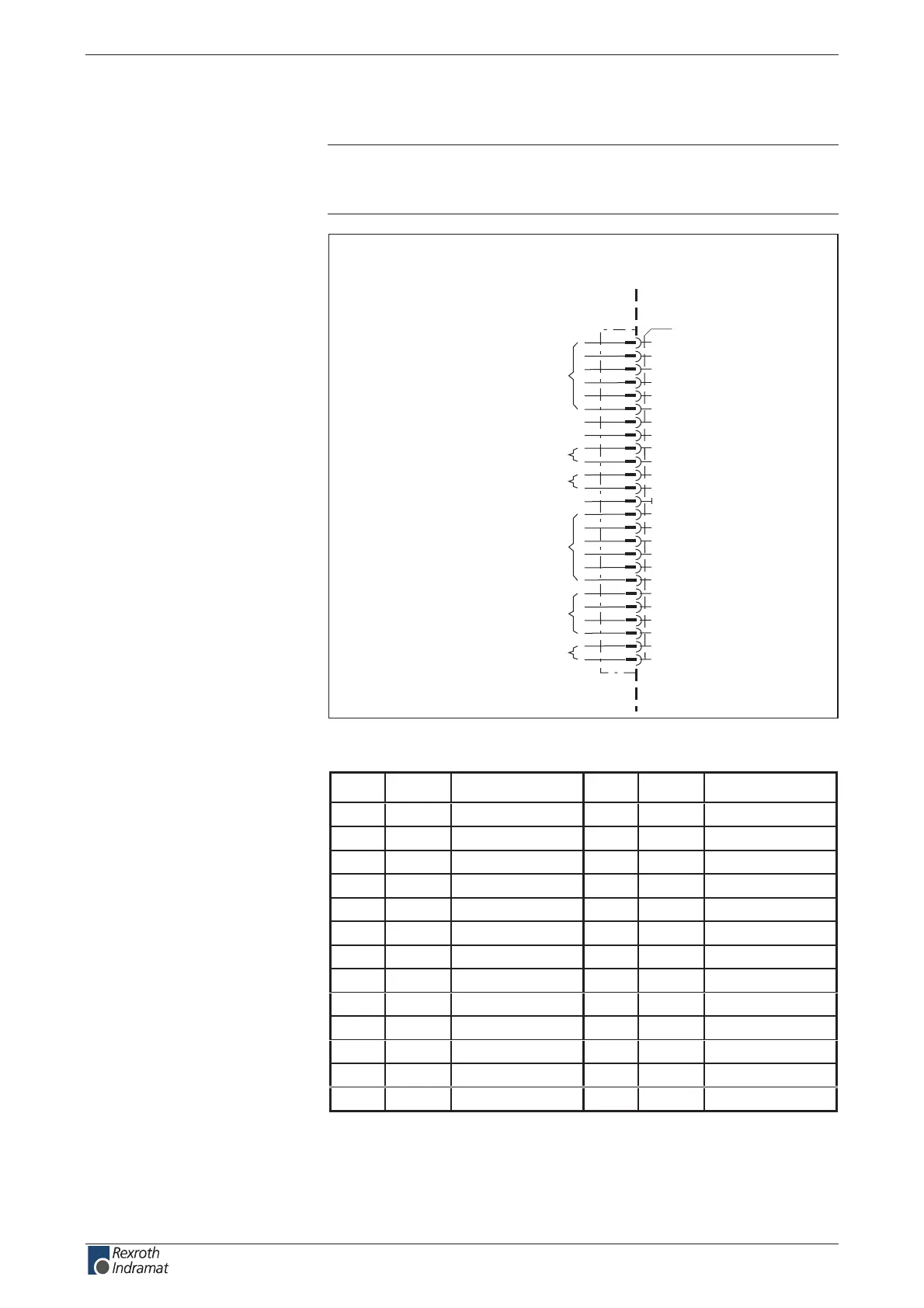
Connection diagram for Parallel Interface
Note: If a power supply other than the DC24 volts of the DKC
controls the inputs, then connect the standard lead (GND) of
the separate mains section to X15.13 (0 V).
DKC01.3
Acknowledge
positioning
input signals
Status messages
Positioning
input signals
Positioning block transfer
selection for going to the zero point
Jog mode
Stepper motor input
Parallel interface
Stepper motor input
AP5029F1.FH5
1
3
4
5
6
7
8
9
10
11
X15
12
13
14
15
16
17
18
19
20
21
22
23
24
25
2
device-external device-internal
I6
I7
I8
I9
SM1+
SM1-
0V
Q0
Q1
Q2
Q3
I5
I1
I2
I0
I3
I4
Q4
Q5
Q6
Q7
Q8
Q9
SM2+
SM2-
default settings:
Fig. 4-162: Parallel interface for DKC01.3
Pin IO Function Pin IO Function
1 I I 0 14 O Q 0
2 I I 1 15 O Q 1
3 I I 2 16 O Q 2
4 I I 3 17 O Q 3
5 I I 4 18 O Q 4
6 I I 5 19 O Q 5
7 I I 6 20 O Q 6
8 I I 7 21 O Q 7
9 I I 8 22 O Q 8
10 I I 9 23 O Q 9
11 SM1+ Di input+ 24 SM2+ Di input+
12 SM1- Di input- 25 SM2- Di input-
13 0V 0V -- -- --
Fig. 4-163: Signal assignment X15
Via D-subminiature mounting screws and metal connector housing.
Connection
Parallel Interface:
Plug-in connector assignment
X15:
Shield connection:
customerservice@hyperdynesystems.com | (479) 422-0390

 Loading...