ECODRIVE03 Drive Controllers ECODRIVE03 DKC**.040, DKC**.100, DKC**.200 4-99
Pin Inputs Pin Outputs
1 I 0 Pos 0 14 Q 0 PosQ 0
2 I 1 Pos 1 15 Q 1 PosQ 1
3 I 2 Pos 2 16 Q 2 PosQ 2
4 I 3 Pos 3 17 Q 3 PosQ 3
5 I 4 Pos 4 18 Q 4 PosQ 4
6 I 5 Pos 5 19 Q 5 PosQ 5
7 I 6 Start 20 Q 6 End position reached
8 I 7 Start home 21 Q 7 standstill
9 I 8 Jog + 22 Q 8 in reference
10 I 9 Jog - 23 Q 9 position switching
point
13 0V 0V
Fig. 4-164: Default allocation of I/Os
Note: The I/O allocation can be congured.
=> See rmware functional description.
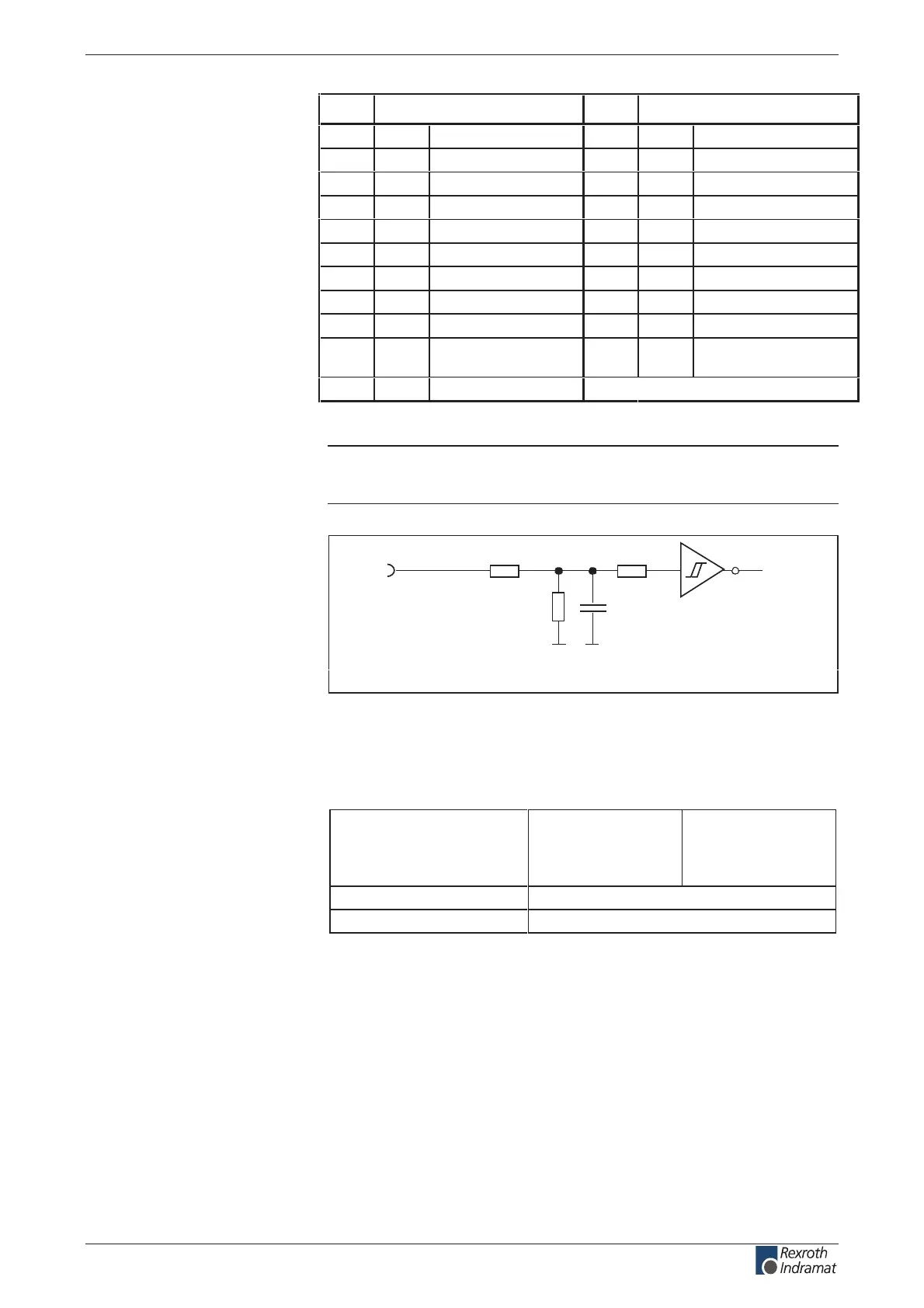
R1 R3
R2
C1
I
n
Ap5183f1.fh7
Schematics
R1: 10k
R2: 3k3
R3: 10k
C1: no data
Fig. 4-165: Input circuit
Input voltage:
High
Low
min.
16 V
-0.5 V
max.
30 V
3 V
%5± mhOk 3.31ecnatsiser tupnI
noitpircsed lanoitcnuf erawmrif ees >=emit noitcaer
Fig. 4-166: Inputs
Default allocation of the binary
I/Os:
Input circuit
I 0 – I 9:
Signal range of inputs
I 0 – I 9:
customerservice@hyperdynesystems.com | (479) 422-0390

 Loading...