4-100 ECODRIVE03 DKC**.040, DKC**.100, DKC**.200 ECODRIVE03 Drive Controllers
Ap5184f1.fh7
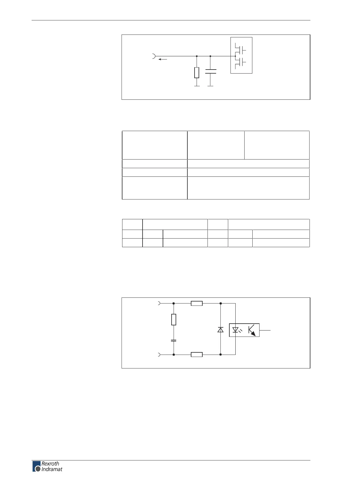
R1
C1
Q
n
I
out
Schematics
R1: 20k
C1: no data
Fig. 4-167: Output circuit
Output voltage:
High
Low
min.
16 V
-0.5 V
max.
U
ext
(an X1.1-1V) – 1.5 V
Output current I
out
80 mA
sn 006 < tuobaemit pord dna esir
overload protection - short circuit protection;
at I
out
> 300 mA outputs switch o
- thermal o
Fig. 4-168: Outputs
Pin Inputs Pin Outputs
11
SM1+
Di input 24
SM2+
Di input
12
SM1-
Di input 25
SM2-
Di input
Fig. 4-169: Default allocation of step motor inputs
The stepper motor inputs are galvanically isolated from the drive
controller. They function as dierential inputs to process RS422
compatible signals.
Ap5185f1.fh7
R2
SM-
R3
R1
C1
SM+
Schematics
R1: 121R
R2: 121R
R3: 121R
C1: 1 nF
Fig. 4-170: Dierential input circuit
Output circuit
Q 0 – Q 9:
Signal level of outputs
Q 0 – Q 9:
Default allocation of step-motor
inputs:
Stepper motor inputs
SM1+, SM1-, SM2+, SM2
Circuit:
customerservice@hyperdynesystems.com | (479) 422-0390

 Loading...