4-106 ECODRIVE03 DKC**.040, DKC**.100, DKC**.200 ECODRIVE03 Drive Controllers
The transmitter power is set with the switches S20/2 and S20/3.
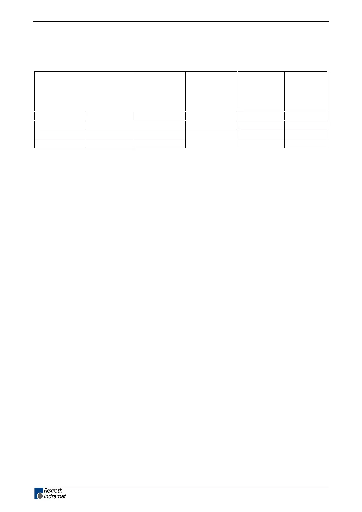
The following table demonstrates the relationship between switch position
and transmitter power.
Switch
position
S20/2
Switch
position
S20/3
Transmission
power at
optimum high
level in
dBm
Transmission
power at
optimum high
level in
µW
Maximum
length with
plastic
ber optic
(*1)
Maximum
length with
glass
ber optic
(*1)
OFF OFF -7 200 0...15 m --
ON OFF -4,5 350 15...25 m --
OFF ON -1 800 25...35 m --
ON ON 0 1000 35...50 m 0...500 m
Fig. 4-179: Relationship between switch position S20/2, S20/3 and the data rate
(*1): The data for the maximum lengths of the ber optic cable only apply
if the following preconditions have been met:
• Rexroth Indramat ber optic cables IKO 982, IKO985 or IKO 001 are
used
• Connection without separation. If couplings are used, the maximum
length for plastic ber optic cables is reduced by about 10 meter, 100
meters for glass ber optic cables.
Fiber optic cables
Drives with a SERCOS interface are connected to higher-level controls
with a ber optic cable.
The ber optic cables (cables, connectors or complete leads) must be
ordered separ
ately.
For more information, see "Fiber optic cables “ in application description
"LWL-Handling" (DOK-CONNEC-CABLE*LWL-AWxx-EN-P).
"LWL-Handling" discusses:
• Fiber optics in general
• Basic plans for optical transmission systems
• Routing guidelines for ber optic cables
• Attenuation readings of standard LWL cables
• Available ber optic-FSMA plug-in connectors and ber optic cables
• Guidelines on making an FSMA connector
• Tools for making ber optic cables
Use the following illustration to nd out which ber optic cable to order.
Transmitter power
customerservice@hyperdynesystems.com | (479) 422-0390

 Loading...