ECODRIVE03 Drive Controllers ECODRIVE03 DKC**.040, DKC**.100, DKC**.200 4-109
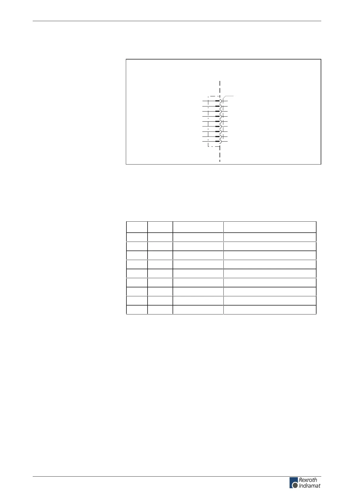
Connection diagram for Probus-DP Interface
DKC03.3
n.c.
n.c.
B
CNTR-P
BUSGND
VP
n.c.
A
CNTR-N
X30
Repeater control signal P
Busground
Receive/transmit data P
Bus 5 V
Receive/transmit data N
1
2
3
4
5
6
7
8
9
AP5050F1.FH7
Probus-DP Interface
device-external device-internal
Repeater control signal N
Fig. 4-184: Probus-DP interface for DKC03.3
As per DIN EN 50 170
as per DIN EN 50 170 – 2, cable type A
Pin DIR Signal Function
.c.n--1
.c.n--2
3 I/O RS485+ receive/transmit data plus
4 O CNTR-P Repeater control signal
V 0V 05
6 O +5 V Repeater supply
.c.n--7
8 I/O RS485- receive/transmit data minus
V 0V 09
Fig. 4-185: Signal assignment of connector X30
Via D-subminiature screws and metal connector housing.
Connection
Probus-DP interface:
Interface compatibility:
Recommended cable type:
Plug-in connector assignment
X30:
Shield connection:
customerservice@hyperdynesystems.com | (479) 422-0390

 Loading...