ECODRIVE03 Drive Controllers ECODRIVE03 DKC**.040, DKC**.100, DKC**.200 4-115
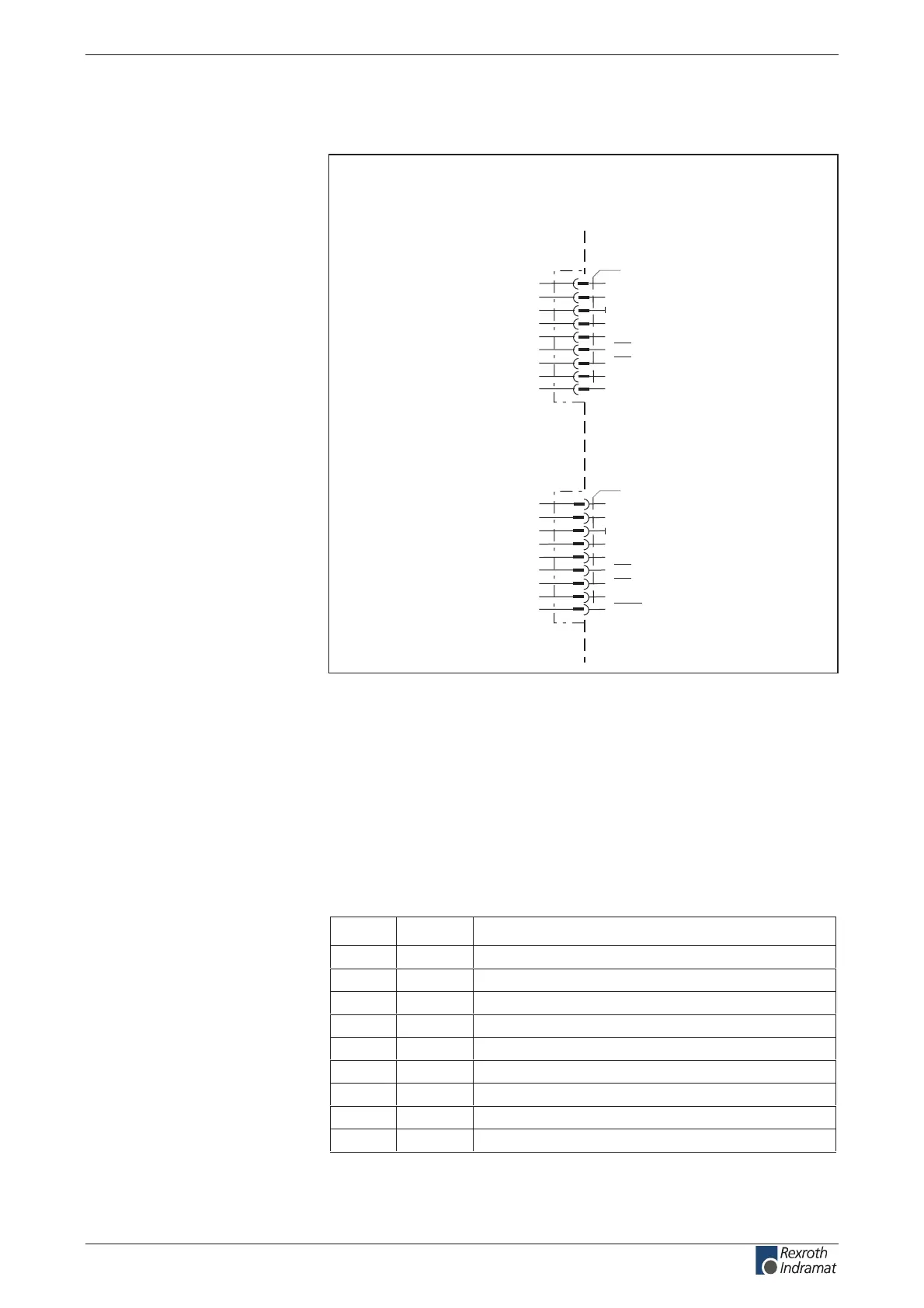
Connection diagram for InterBus Interface
DKC04.3
D02(output)
DI2(input)
0V
n.c.
+5V(output)
D02(output)
DI2(input)
n.c.
RBST(input)
X41
1
2
3
4
5
6
7
8
9
AP5162F1.FH7
InterBus interface
D01(input)
DI1(output)
0V
n.c.
n.c.
D01(input)
DI1(output)
n.c.
n.c.
X40
1
2
3
4
5
6
7
8
9
device-external device-internal
device-external device-internal
outgoing Interface
incoming interface
Fig. 4-196: InterBus Interface for DKC04.3
as per DIN EN 50 254 - 1
as per DIN EN 50 254 - 1
as per DIN EN 50 254 - 1
as per DIN EN 50 254 - 2
noitinifedRIDniP
1ODI1
1IDO2
V0O3
.c.n--4
.c.n--5
1OD/I6
1ID/O7
.c.n--8
.c.n--9
Fig. 4-197: Allocation of interface signals X40, Incoming interface
Connection
InterBus Interface:
Interface compatibility
Signal specication
Lead length:
Recommended cable:
Plug-in connector assignment
X40
Incoming interface:
customerservice@hyperdynesystems.com | (479) 422-0390

 Loading...