4-116 ECODRIVE03 DKC**.040, DKC**.100, DKC**.200 ECODRIVE03 Drive Controllers
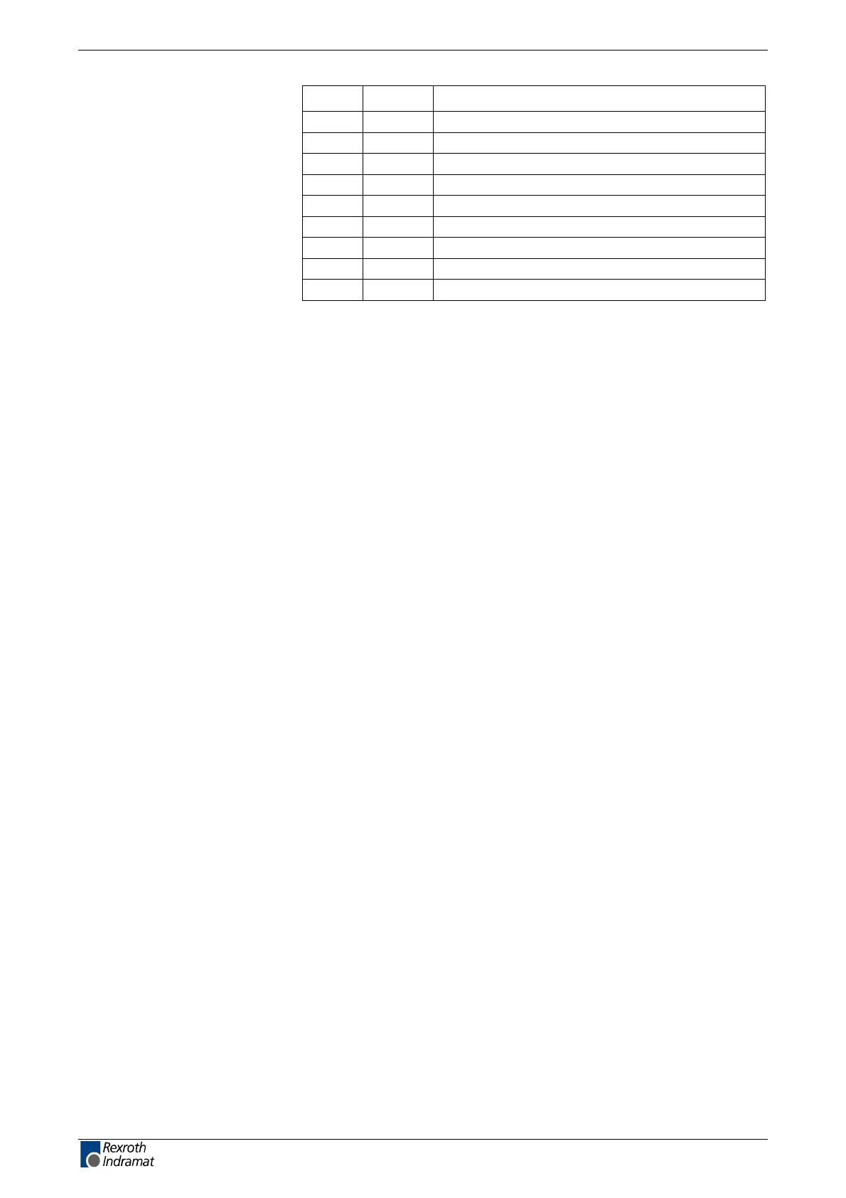
noitinifedRIDniP
2ODO1
2IDI2
V0O3
.c.n--4
V5 +O5
2OD/O6
2ID/I7
.c.n--8
TSBR/I9
Fig. 4-198: Allocation of interface signals X41, outgoing interface
Via D-subminiature mounting screws and metal connector housing.
as per DIN EN 50 254 - 1
Incoming and outgoing interfaces must be isolated from each other and
galvanically from the controller.
The denition of the displays are in the rmware function description.
Plug-in connector assignment
X41
outgoing interface:
Shield connection:
Signal specication:
Diagnostics display
H40 – H45:
customerservice@hyperdynesystems.com | (479) 422-0390

 Loading...