4-124 ECODRIVE03 DKC**.040, DKC**.100, DKC**.200 ECODRIVE03 Drive Controllers
Ap5184f1.fh7
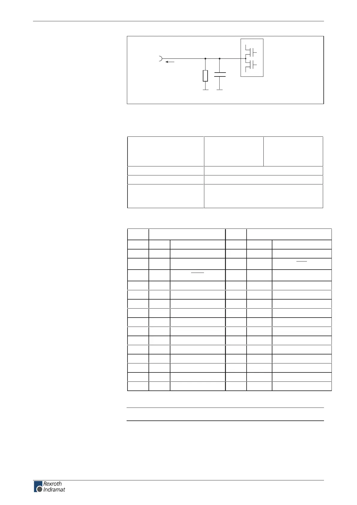
R1
C1
Q
n
I
out
Schematics
R1: 20k
C1: no data
Fig. 4-217: Output circuit
Output voltage:
High
Low
min.
16 V
-0.5 V
max.
U
ext
1.5 V
Output current I
out
80 mA
sn 006 < tuobaemit pord dna esir
overload protection - short circuit protection;
at I
out
> 300 mA outputs switch o
- thermal o
Fig. 4-218: Outputs
Pin Inputs Pin Outputs
1 I 0 Parameter 17 Q 0 Hand
2 I 1 Hand / Auto 18 Q 1 Auto
3 I 2 Start 19 Q 2
Error
4 I 3
STOP
20 Q 3 Run
5 I 4 Jog+ 21 Q 4 Output 01
6 I 5 Jog- 22 Q 5 Output 02
7 I 6 Input 01 23 Q 6 Output 03
8 I 7 Input 02 24 Q 7 Output 04
9 I 7 Input 03 25 Q 8 Output 05
10 I 9 Input 04 26 Q 9 Output 06
11 I 10 Input 05 27 Q 10 Output 07
12 I 11 Input 06 28 Q 11 Output 08
13 I 12 Input 07
14 I 13 Input 08
15 I 14 Input 09
16 I 15 Input 10
Fig. 4-219: Default allocation of the inputs and outputs
Note: Inputs 01 ... 10 and Output 01 ... 08 can be congured.
Output circuit connection Q 0 –
Q 11:
Output connection
Q 0 – Q 11:
Default allocation of binary I/Os:
customerservice@hyperdynesystems.com | (479) 422-0390

 Loading...