5-40 srellortnoC evirD 30EVIRDOCE610-3.**CKD 30EVIRDOCE
wire cross section:
min. 1 mm ²
voltage resistance of single wire to ground
> 750 V
(e.g.: litz wires - H07)
wire routing
parallel if possible
(twisted)
max. inductance between 24 V source
and X6
100 µH
(equals about 2 x 75 m)
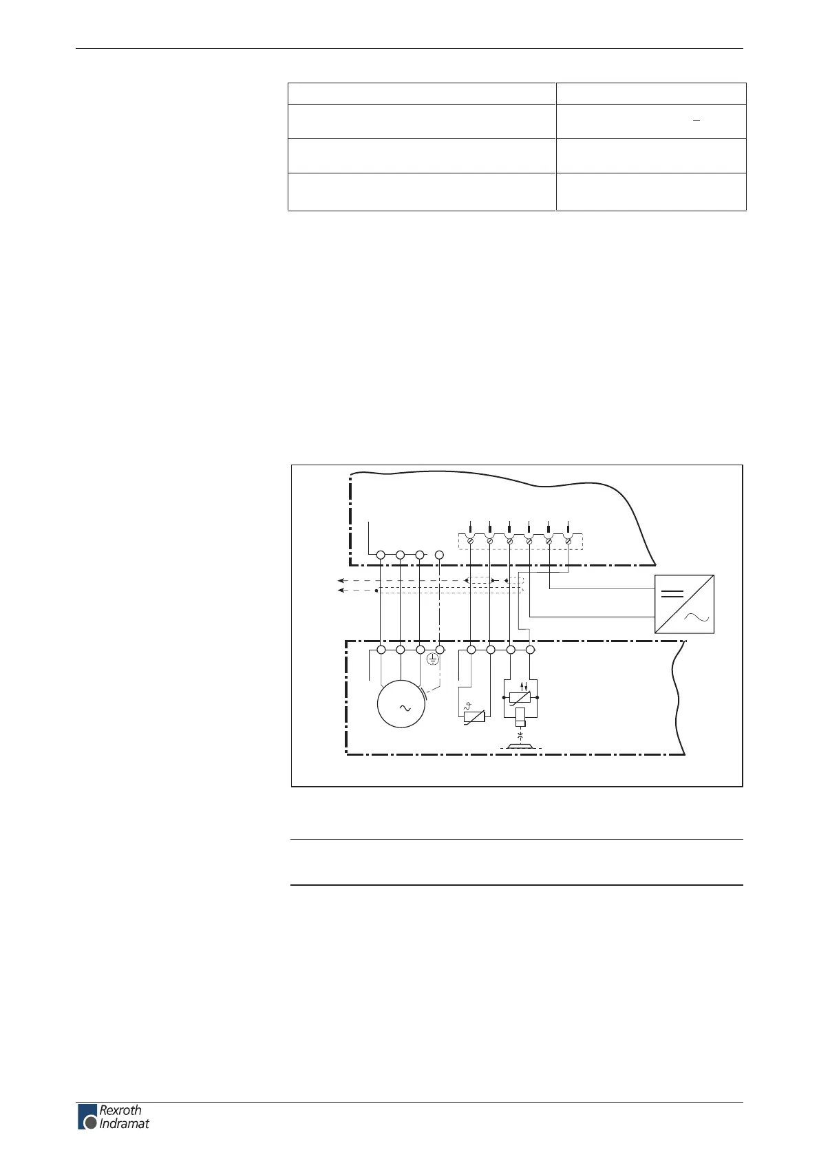
Motor holding brake
The controller controls the holding brake.
Supply voltage, current consumption, linking, separating time, holding
torque, etc. see motor manual.
Basic connection of motor power, holding brake and
motor temperature monitoring
AP5387F1.FH7
AC-Motor
M
3
U1
V1
W1
X1 X2
T1
T2
U
BR-
BR+
3
4
1
2
A1 A2 A3
X6
5
6
TM+
TM-
BR+
BR-
U
B
0V B
24V
Ext
0V
Ext
DKC
XE1
X5_M
24V
XS1
Temperature
dependent resistance
Holding
brake
Fig. 5-66: Connection of motor cable, holding brake and temperature monitor
for motors with connector box
Note: The cable designations and all details on making cables are
outlined in the cable or motor document.
wire
voltage connection for brake:
Controlling the motor holding
brake:
Technical data
Motor holding brake:
customerservice@hyperdynesystems.com | (479) 422-0390

 Loading...