6-14 ECODRIVE03 Auxiliary Bleeder Module BZM01.3 ECODRIVE03 Drive Controllers
L1
L2
L3
R
ZKS
L+
L-
Ap5416f1.fh7
t
d
&
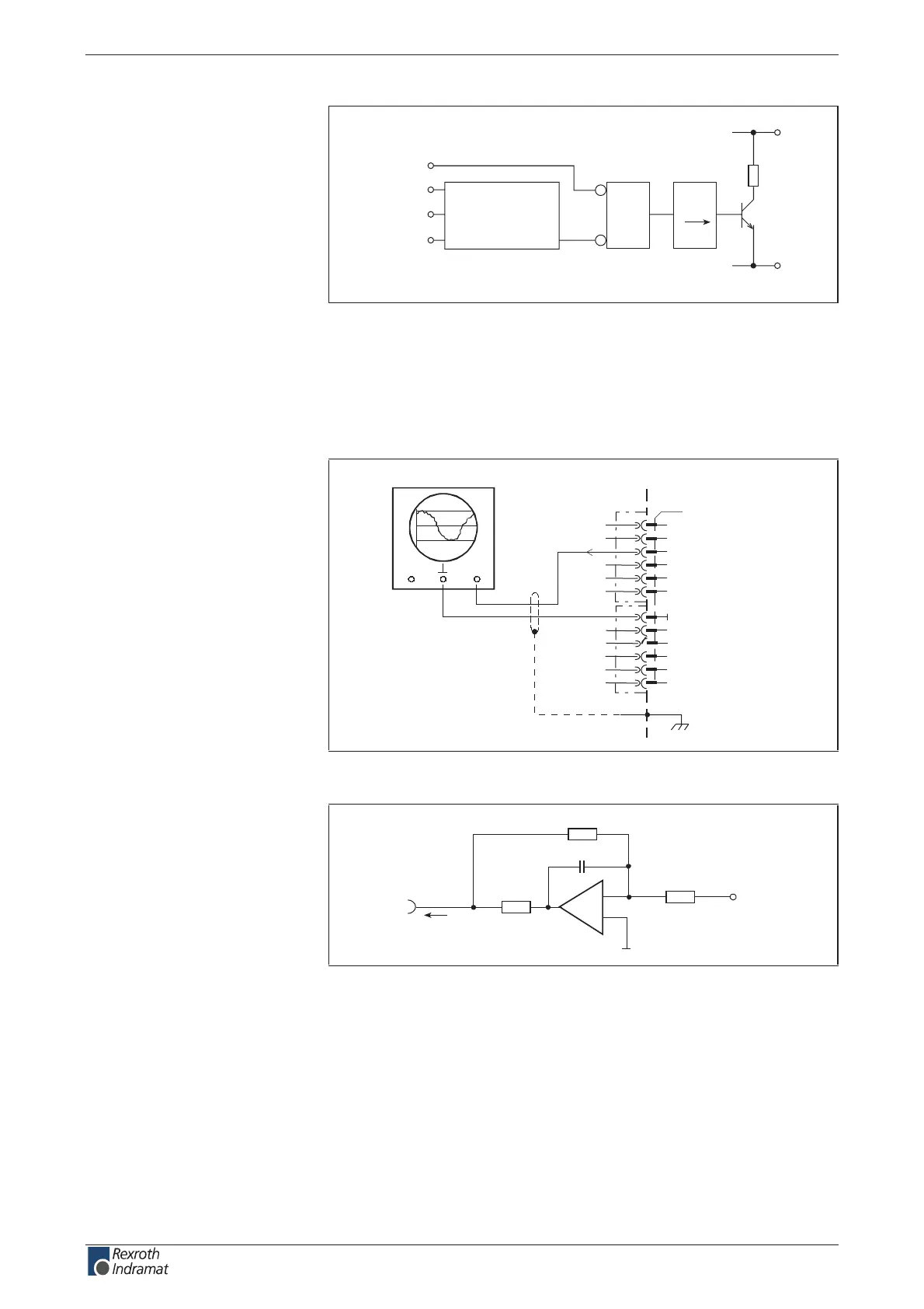
Mains voltage:
applied: "H"
not applied: "L"
ZKS input:
with current: "H"
without current: "L"
Fig. 6-25: Block diagram interlock ZKS/Mains
Also see page 4-25: "Arranging the Central supply" and
page 11-5: "Control Circuits with internal DC bus dynamic brake (ZKS)".
Analog Output Load:
AP5306F1.FH7
for example: oscilloscope
CH2 CH1
XS2
X2
1
2
3
4
5
6
7
8
10
11
12
Load
0V
9
Fig. 6-26: Output load
AP5307F1.FH7
R3
R2
-
+
C1
Q
n
I
out
R1
R1: 150R
R2: 20k
R3: 10k
C1: no data
Fig. 6-27: Output circuit
Connection:
Output circuit
Load:
customerservice@hyperdynesystems.com | (479) 422-0390

 Loading...