ECODRIVE03 Drive Controllers ECODRIVE03 Auxiliary Bleeder Module BZM01.3 6-15
Output voltage
between load and 0 V:
min
0 V
max.
10 V
Am 2 .xaMtnerruc tuptuo
atad onretrevnoc AD
atad ontib rep noituloser
short circuit and overload
protection
not present
evaluation
BZM,BD
P
V10
U
•
Fig. 6-28: Output load
The connection is used to output an analog signal of the proportional load
of the mounted bleeder resistor.
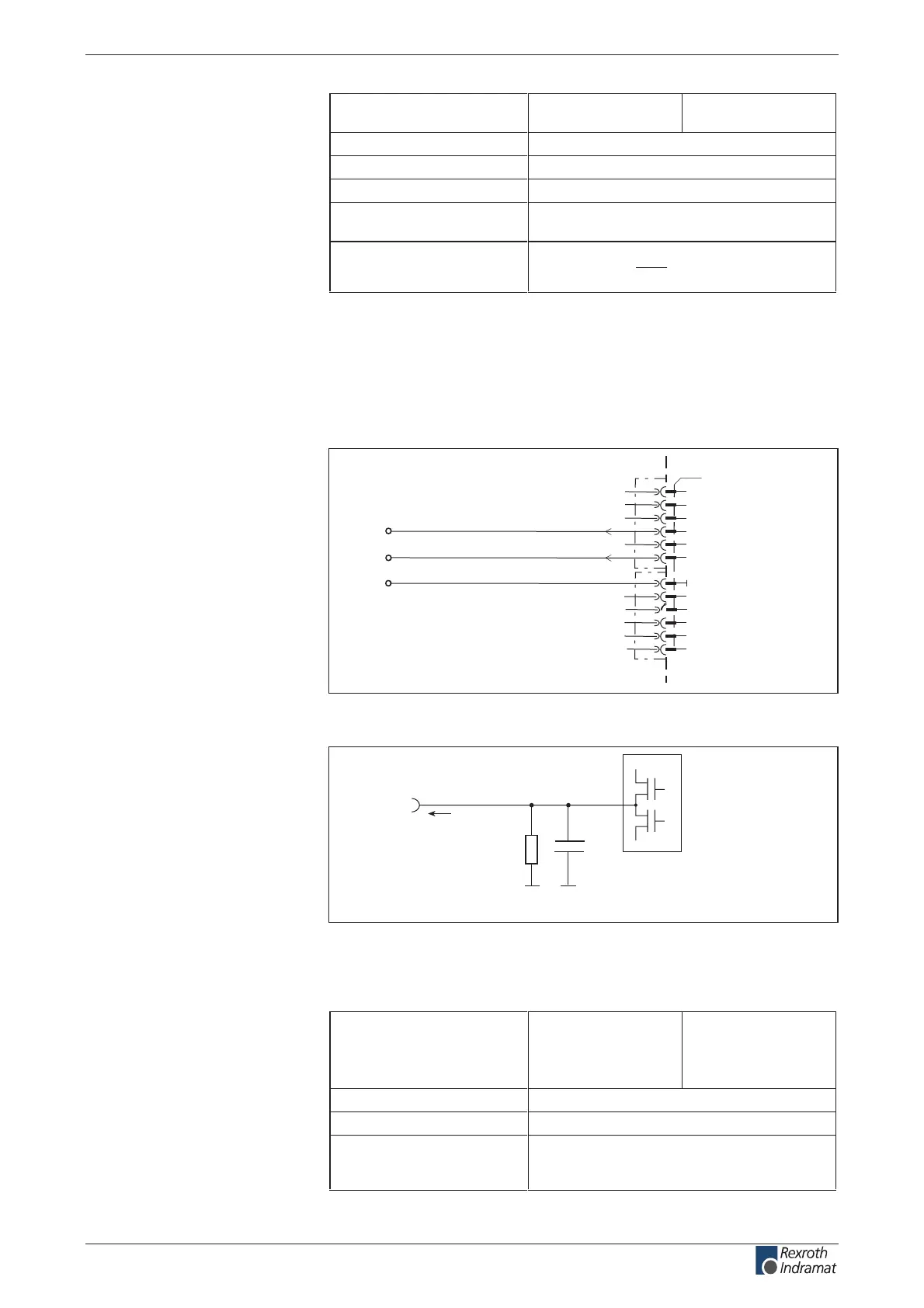
Ready, Warning:
AP5309F1.FH7
Warning message
0V
ext
Ready message
X2
1
2
3
4
5
6
7
8
10
11
12
Ready
Warning
9
0V
Fig. 6-29: Output Ready, Warning
Ap5184f1.fh7
R1
C1
Q
n
I
out
Schematics
R1: 20k
C1: 1nF
Fig. 6-30: Output circuit
Output voltage:
High
Low
min.
16 V
-0.5 V
max.
U
ext
(an X1.1-1V)
1.5 V
Output current I
out
80 mA
sn 006 < tuobaemit pord dna esiR
Overload protection - short circuit protection
at I
out
> 300 mA outputs switch o
- thermal shutdown
Fig. 6-31: Outputs Ready, Warning
Output
Load:
Load:
Connection
Ready, Warning:
Output circuit
Ready, Warning:
Outputs
Ready, Warning:
customerservice@hyperdynesystems.com | (479) 422-0390

 Loading...