6-18 ECODRIVE03 Auxiliary Bleeder Module BZM01.3 ECODRIVE03 Drive Controllers
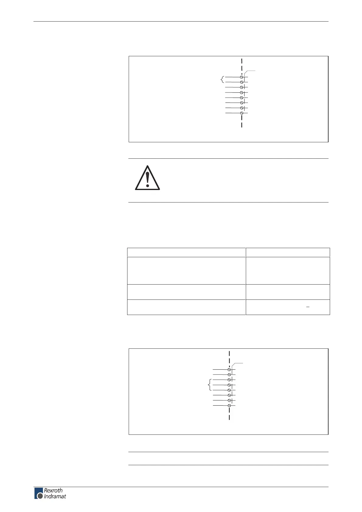
DC bus connection
device-external device-internal
AP5301F1.FH7
X5
L+
L-
DC bus connection
Fig. 6-39: Connection DC bus
CAUTION
Damage possible if DC bus connections L+ and
L- are reversed!
Make sure polarity is correct.
If the DC bus rails supplied do not make a connection possible, then use
short twisted wires to do so.
wire length:
max. 2 x 1 m
wire cross section:
min. 10 mm ²,
not smaller than the cross
section of the mains supply
lead
wire protection
With a fuse in the mains
connections
Voltage resistance of individual wires to
ground
> 750 V
(e.g., litz wires - H07)
Motor connection
device-external device-internal
AP5371F1.FH7
X5
A1
A2
A3
n.c.
Fig. 6-40: Motor connection
Note: Connections A1, A2, A3 are not wired!
Connection
DC bus:
wire
DC bus
Motor connection:
customerservice@hyperdynesystems.com | (479) 422-0390

 Loading...