4-14 ECODRIVE03 DKC**.040, DKC**.100, DKC**.200 ECODRIVE03 Drive Controllers
WF-7-002-3.**CKDtinUlobmySnoitangiseD
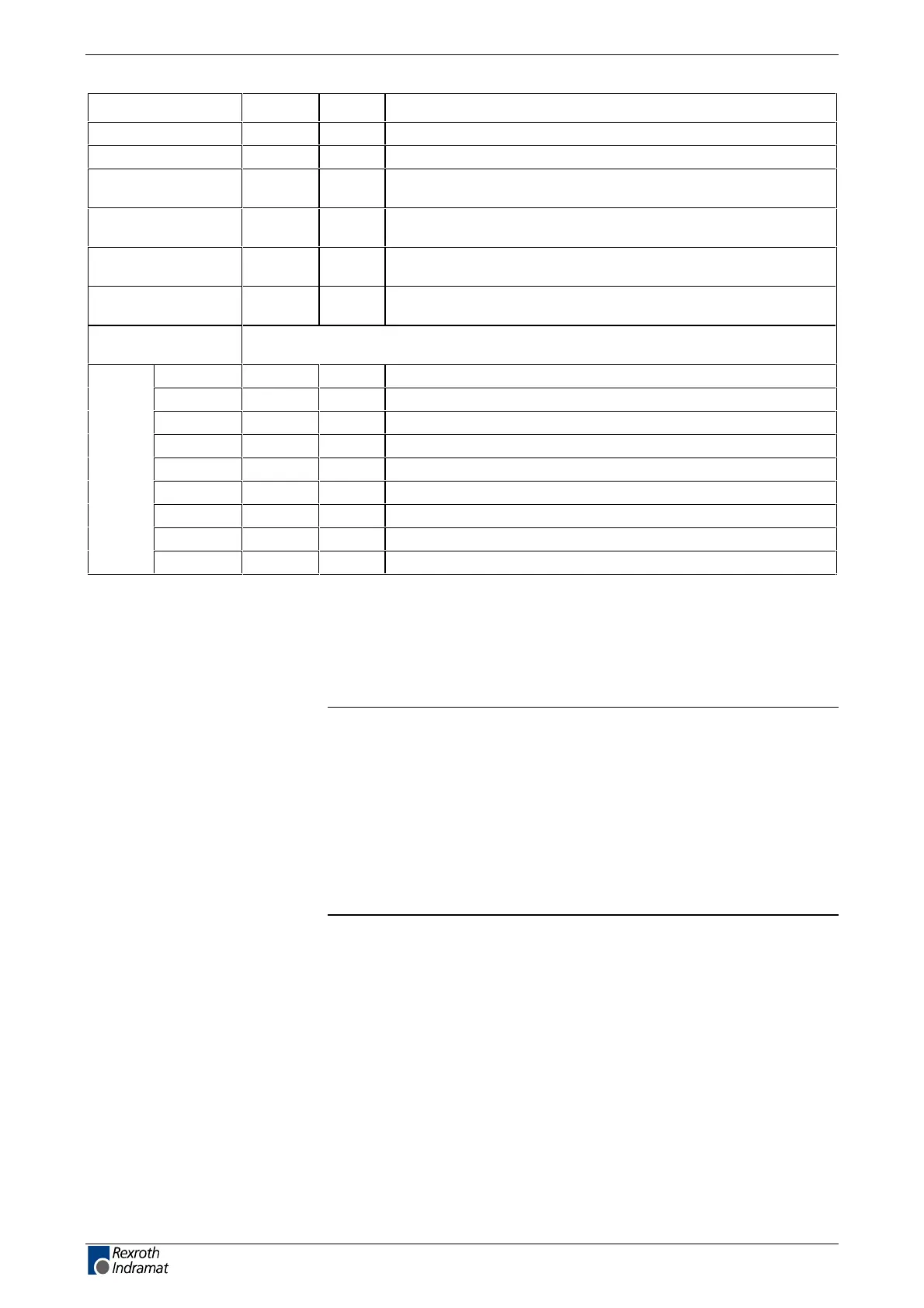
Control voltage U
N3
V )8.82 ... 2.91( CDV
egnar egatlov tupni deecxe ton yamwtceffe elppir .xam
max. allowed
overvoltage
U
N3max
* evititeper non ,sm1 rof V 54V
)
max. charging
current
I
EIN3
0.6A
max. pulse duration
of I
EINmax
t
N3Lade
9sm
max. input
capacitance
C
N3
2.1 * 0.1Fm
Power consumption
(X1)
dependent on type of unit, without external load at control outputs and
encoder interface 2
DKC01.3 P
N3
72W
DKC02.3 P
N3
72W
DKC03.3 P
N3
82W
DKC04.3 P
N3
92W
DKC05.3 P
N3
82W
DKC06.3 P
N3
82W
DKC11.3 P
N3
62W
DKC21.3 P
N3
82W
DKC22.3 P
N3
82W
Fig. 4-12: Control voltage connection for DKC
*
)
To be obtained by appropriate mains sections and shielded wire routing.
Connections for control voltage: see page 4-45 X1, Connections for
Control voltage.
Note: Overvoltages of more than 45 V have to be derived by
measures in the electrical equipment of the machine or
installation. This includes:
• 24-Volt mains sections that reduce incoming overvoltages
to the allowed value.
• Overvoltage limiters at the control cabinet input that limit
existing overvoltages to the allowed value. This also
applies to long 24-Volt lines that have been laid in parallel
with power and mains cables and can absorb overvoltages
caused by inductive or capacitive coupling.
customerservice@hyperdynesystems.com | (479) 422-0390

 Loading...