ECODRIVE03 Drive Controllers ECODRIVE03 DKC**.040, DKC**.100, DKC**.200 4-15
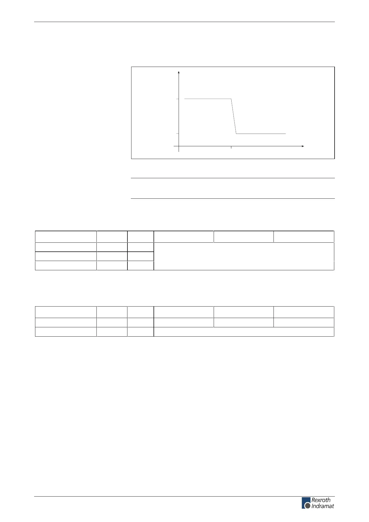
Amplitude of the DKC control voltage charging current at
startup, to selecting power source
time
current
I
EIN3
I
Nenn
t
N3Lade
Fig. 4-13: Example of charging current inrush of control voltage
Note: For n parallel-switched inputs the charging current inrush is
n-fold.
Voltage connection for holding brake
Designation Symbol Unit DKC**.3-040-7-FW DKC**.3-100-7-FW DKC**.3-200-7-FW
Input voltage U
HB
V depends on motor type, listed in motor project planning manual
Ripple content w %
Current consumption I
HB
A
(see also page 4-67 X6, Motor temperature monitoring and holding
brakes)
Fig. 4-14: Voltage connection for holding brake
Materials used, Mass
Designation Symbol Unit DKC**.3-040-7-FW DKC**.3-100-7-FW DKC**.3-200-7-FW
5.917.97.5gkmssaM
enocilis dna sotsebsa fo eerFdesu slairetam
Fig. 4-15: Materials used, mass
customerservice@hyperdynesystems.com | (479) 422-0390

 Loading...