RFL 9780 RFL Electronics Inc.
April 8, 2003 6-14 (973) 334-3100
6.4.10 CONFIGURATION OF ALARM PICK-UP/ALARM DROP-OUT TIMERS
Alarm Pick-Up (APU): The position of switches SW6-1 through SW6-4 determines the amount of
alarm condition required for the logic module to go into an alarm state.
Alarm Drop-Out (ADO): The position of switches SW6-5 through SW6-8 determines the amount of no
alarm condition required for the logic module to return to normal no alarm state.
The time period shown in Table 6-13 for each switch position is cumulative. A switch is in the ON
position enables its corresponding time period. The selectable timer range is either 50ms or between
100ms and 1500ms in increments of 100ms. When switches (SW6-1 through SW6-4) are in the OFF
position, the APU is configured for 50ms. When switches (SW6-5 through SW6-8) are in the OFF
position, the ADO is configured for 50ms.
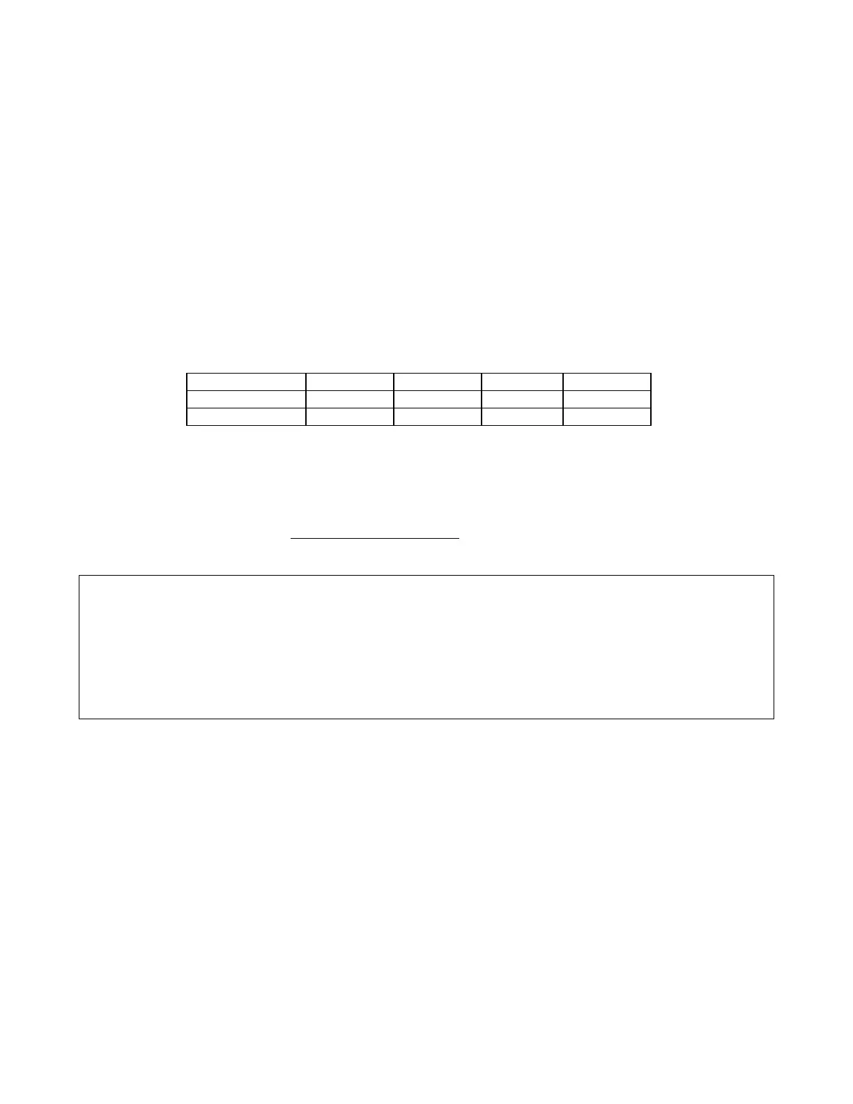
Table 6-13. Configuration of Alarm Pick-Up / Alarm Drop-Out Timers
APU Switch SW6-1 SW6-2 SW6-3 SW6-4
ADO Switch SW6-5 SW6-6 SW6-7 SW6-8
Time (ms) 800 400 200 100
Example: The Alarm Drop-out Timer configured for a time period of 1000ms would be set as follows:
SW6-5: ON 800ms
SW6-6: OFF 0ms
SW6-7: ON 200ms
SW6-8: OFF 0ms
TOTAL 1000ms
NOTE
Because many of the timer functions interact, careful selection of these is necessary. When
GBT/TAG is enabled, the alarm pickup timer must be set to a value greater than the TAG
setting. It is also recommended that the alarm dropout timer be set to a value less than the GBT
setting.
6.4.11 CONFIGURATION OF TRIP LATCH OPTION
The position of switch SW7-1 determines whether the Trip Latch option is enabled. Placing SW7-1 in
the ON position enables the Trip Latch option. The Trip Latch option latches the LEDs for Trips that
are transmitted and received. The Trip Sent relay, which picks-up when a Trip is transmitted is latched
as well. Pushbutton switch SW11 is used to un-latch the LEDs and the Trip Sent relay once the Trip
condition has been acknowledged.