RFL 9780 RFL Electronics Inc.
April 8, 2003 17-40 (973) 334-3100
P1
C7
CR3
C5
C2
C4
C6
C3
K1
TB1
K2
J1
Q1
C8
J3
CR4
C1
R2
R1
R3
J2
A
A
A
B
B
B
+
1
CBE
+
DUAL RELAY 106473 REV-B
99134
100uF
1N4003
3KV.01uF
3KV.01uF
3KV.01uF
3KV.01uF
3KV.01uF
101461
101461
N/A
22A
2N22
100uF
1N4003
3KV.01uF
.5W162
.5W162
1K
TB
J3
J1
J2
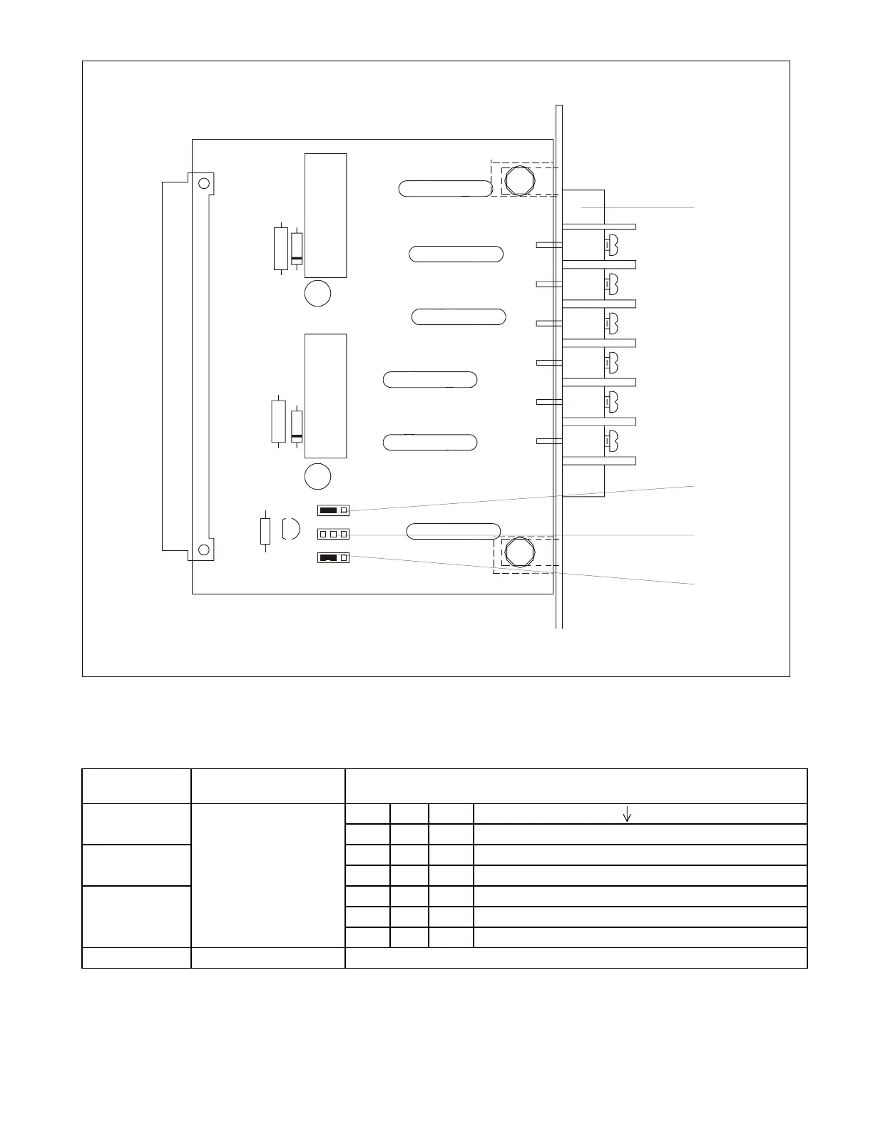
Figure 17-17. Controls and indicators, and component locator drawing, Dual Relay I/O module
Table 17-10. Controls and indicators, Dual Relay I/O module
Component
Designator
Name/Description Function
J1 J1 J2 J3
NC A A one guard output and one trip output (default)
J2 Jumpers A B A two guard outputs
A A NC two trip outputs
J3 NC A B one undefined (spare) and one trip output
B B A one undefined (spare) and one guard output
A B B two undefined outputs (spares)
TB1 Terminal block Provides connections to line coupling equipment