RFL 9780 RFL Electronics Inc.
April 8, 2003 14-6 (973) 334-3100
14.4 CONTROLS AND INDICATORS
Figure 14-3 shows the location of all controls and indicators on the RFL 9780 Limiter/Slicer module.
These controls and indicators are described in Table 14-1. Only DS1, DS2 and TP1 through TP8 are
accessible with the RFL 9780 Limiter/Slicer Module installed in the chassis. All others are accessible
when the module is removed from the chassis or is on a card extender.
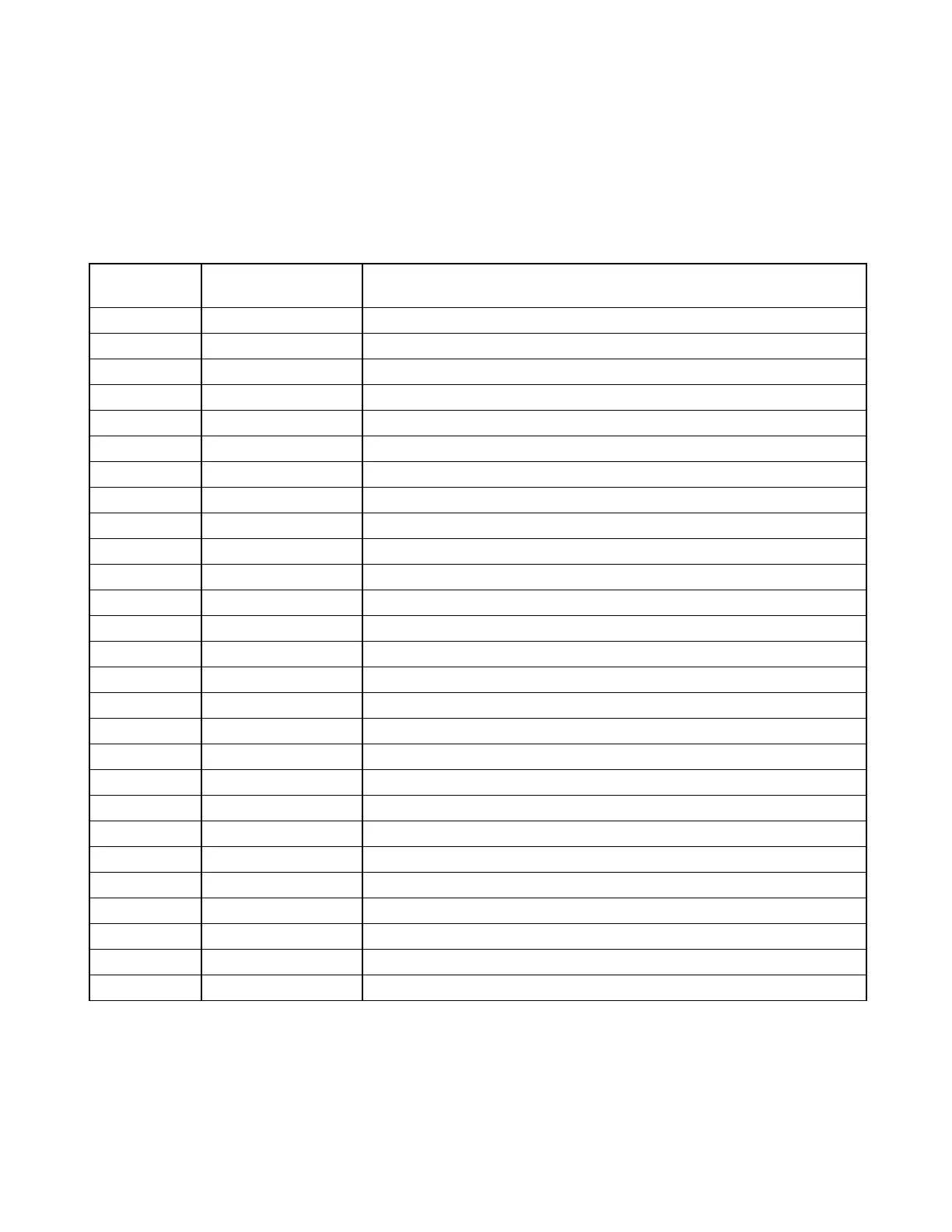
Table 14-1. Controls and indicators, RFL 9780 Limiter/Slicer Module
Component
Designator
Name/Description Function
DS1 Shift Down LED Indicates that the carrier has shifted down from the center frequency
DS2 Shift Up LED Indicates that the carrier has shifted up from the center frequency
J1 Jumper NORM/INV Should always be in the NORM (Normal) position
J2* Jumper TEST/NORM Bypasses the envelope rectifier and filter
R5* Potentiometer Trip slice adjust
R29* Potentiometer Slicer scale
R36* Potentiometer Bias adjust
R49* Potentiometer Guard slice adjust
R58* Potentiometer Discriminator adjust
R77* Potentiometer 60 Hz notch filter adjust
R83* Potentiometer 120 Hz notch filter adjust
R89* Potentiometer 180 Hz notch filter adjust
TP1 Test point, black Signal ground
TP2 Test point terminal Processed signal prior to entering slicing comparators
TP3 Test point terminal Logic high indicates trip
TP4 Test point terminal Logic high indicates guard
TP5 Test point terminal Guard threshold
TP6 Test point terminal Trip threshold
TP7 Test point terminal Shaped input signal (0 Degree reference)
TP8 Test point terminal 90
o
center frequency
TP9 Test point terminal 4 kHz input
TP10 Test point terminal Discriminator output
TP11 Test point terminal Envelope level to 97 PLC Logic (approx 1 Vdc)
TP12 Test point, red +5Vdc
TP13 Test point, orange +15Vdc
TP14 Test point, yellow -15Vdc
TP15 Test point, purple +12Vdc
* For factory use only.