RFL 9780 RFL Electronics Inc.
November 1, 2000 8-3 (973) 334-3100
8.3 THEORY OF OPERATION
The RFL 9780 Transmitter module is a programmable powerline carrier transmitter utilizing a Direct
Digital Synthesizer (DDS). The DDS is used to generate a precise sine wave signal by reading a sine
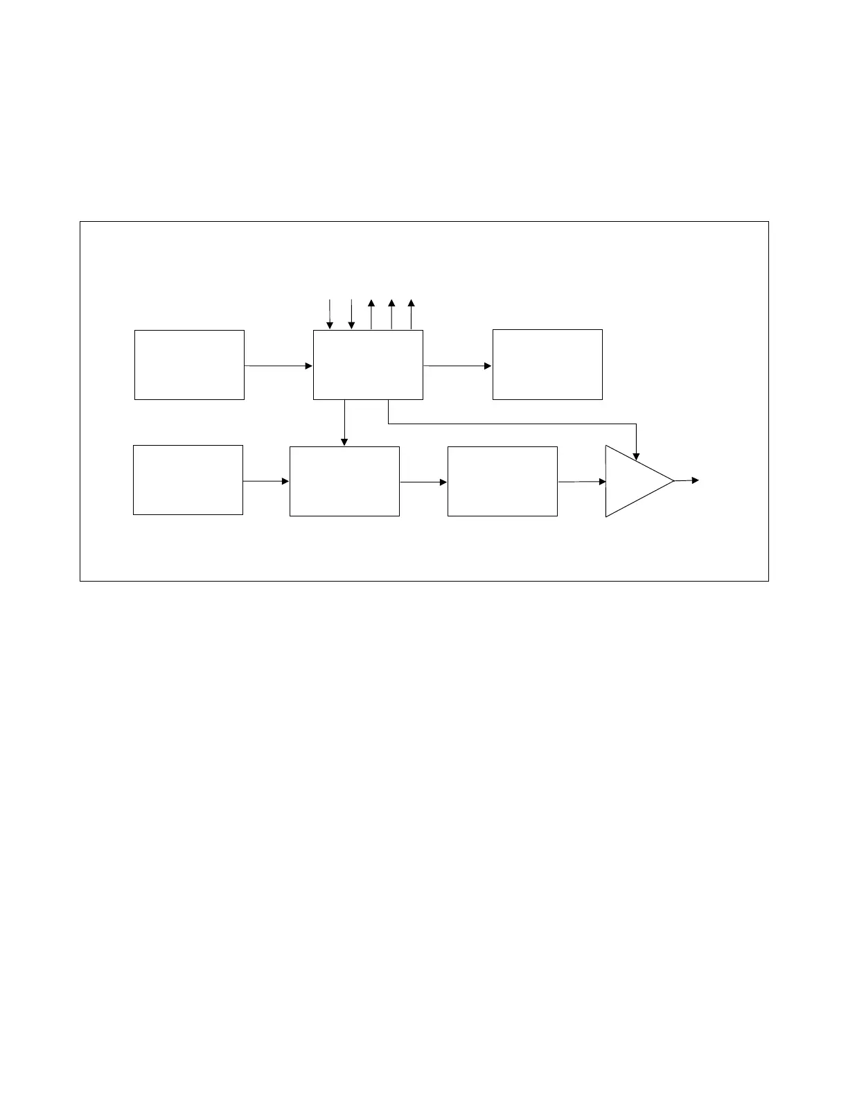
look-up table stored in ROM. A block diagram of the transmitter module is shown in Figure 8-2, a
block diagram of the DDS is shown in Figure 8-3, and a schematic diagram of the transmitter module is
shown in figure 8-5.
Figure 8-2. Transmitter module block diagram
The output of the look-up table is connected to a D/A converter which generates the sine wave. As the
input to the look-up table is incremented, the output of the table via the D/A generates the sine wave.
Thus, the input to the look-up table is related to the phase of the output sine wave. The phase
information is stored in the phase register.
8.3.1 DIRECT DIGITAL SYNTHESIZER FUNDAMENTALS
A simplified block diagram for a basic DSS is shown in Figure 8-3. The circuit has two inputs, a master
clock and a phase step. The master clock should be considerably higher in frequency than the highest
frequency to be generated by the DDS. Once each clock cycle, the phase register is incremented by the
specified phase step amount. The phase register is configured to roll over at 360
o
.
The output of the phase register is sent to a lookup table which generates the value of the sine function
for the given phase. The output of the lookup table is in turn sent to a D/A converter which produces
the desired output voltage. In this manner, as the phase is gradually increased from 0
o
to 360
o
, the D/A
produces a single sine wave cycle. By allowing the phase register to roll over, the output remains
smooth and over time, all discrete phase angles will be sampled.
Configuration
Switches
Field
Programmable
Gate Array
LED Indicators
Precision
50 Mhz Osc
Direct Digital
Synthesizer
(DDS)
Low-Pass
Filter
Gain
dj
Carrier
Out
Control
Signals