RFL 9780 RFL Electronics Inc.
April 8, 2003 17-51 (973) 334-3100
17.7 INPUT/ALARM I/O MODULE
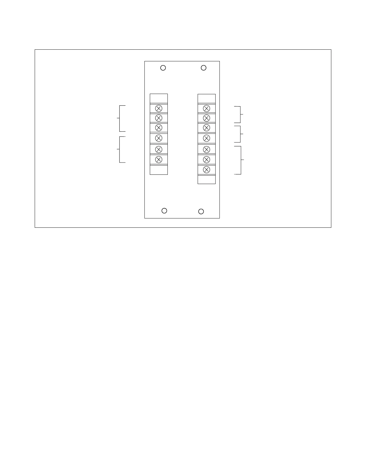
Figure 17-22. Input/Alarm I/O module, rear panel view
17.7.1 DESCRIPTION
The Input/Alarm I/O module (Figure 17-22) is composed of two sections. One section provides solid-
state inputs and the other section provides alarm outputs. This I/O module is available in three versions
as follows:
Input Voltage Assembly No.
48V or 125V (106600-3)
250V (106600-4)
5V (106600-5)
The 48/125V version requires that jumpers J4 and J5 be configured for the input voltage requirement.
J4 and J5 are placed in the 48V or 125V position as required. Voltage selectors J4 and J5 are not
required for 250V operation.
The Input/Alarm I/O module is primarily used for TX/TX applications. It can also be used for customer
specific applications and can be mounted in a spare I/O slot or in an expansion chassis.
INPUT/ALARM
PW
FAI
1 C
2 N
3 N
4 C
5 N
6 N
TX
FAI
+
-
+
-
C
NO
C
POWER SUPPLY
FAIL ALARM
TX FAIL
ALARM
C
NO
NC
C
NO
NC
+1
IN 1
-2
+3
IN 2
-4
C 5
NO 6
NC 7
TX
SENT
TRIP KEY 1
TRIP KEY 2
TRIP SENT