RFL 9780 RFL Electronics Inc.
April 8, 2003 15-5 (973) 334-3100
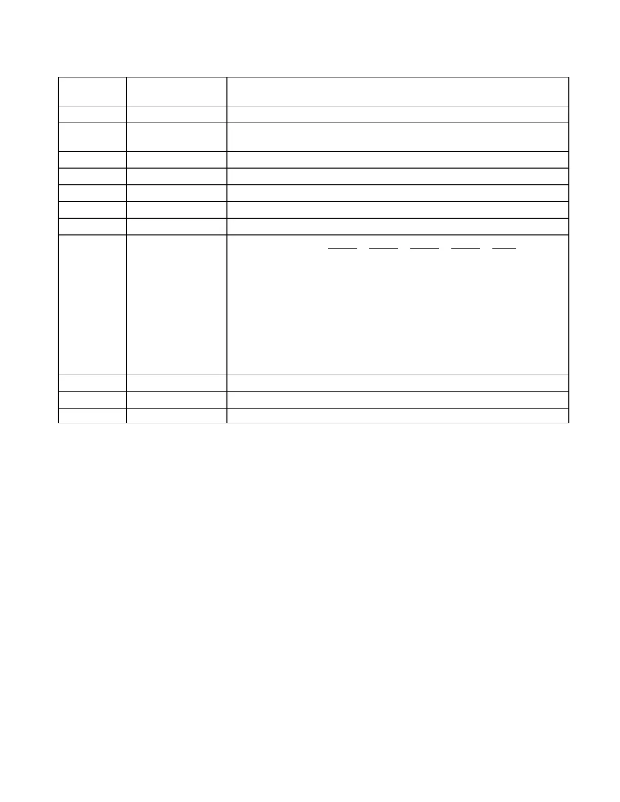
Table 15-2. Controls and indicators for RFL 9780 SOE/IRIG-B Module
Component
Designator
Name/Description Function
J1 Jumper (RUN/TEST) RUN position selects Normal operation. TEST position selects Test operation.
J2 Jumper (512 or
128/256)
Header and jumper not installed. For factory use only.
J3 Jumper (1643/1644) 1643 position selects DS1643 RAM. 1644 position selects DS1644 RAM.
J4 Connector Header Used for factory testing
J5 Jumper (IN/OUT) IN position selects IRIG-B clock. OUT position selects internal clock.
J6 Connector Header For future use
J8 Connector Header RS-232 connector
SW1 (Note 1) DIP Switch Selects Operating
Mode:
SW1-1 SW1-2 SW1-3 SW1-6 Mode
ON ON ON ON 9785
OFF ON ON ON 9780TX/RX
ON OFF ON ON 9780TX/TX
OFF OFF ON ON 9780RX/RX
ON ON OFF ON 9780RX
OFF ON OFF ON 9780TX
ON ON ON OFF SP9785 (Note 2)
TP1 Test Point Ground Reference
TP2 Test Point IRIG-B High
TP3 Test Point IRIG-B Low
NOTE 1: SW1-4, SW1-5, SW1-7 and SW1-8 are for future use. SW1-4, SW1-5 and SW1-7 must be set to ON,
and SW1-8 must be set to OFF.
NOTE 2: For RFL use only