RFL 9780 RFL Electronics Inc.
April 8, 2003 6-28 (973) 334-3100
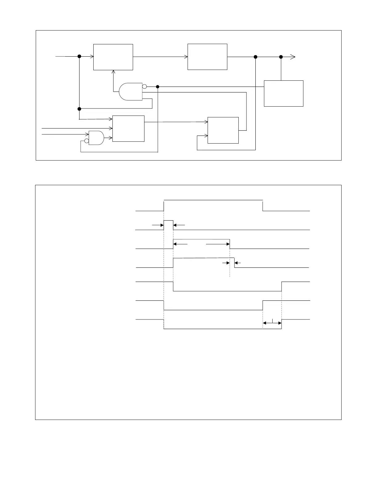
Figure 6-4. Receiver Unblocking Function Logic (part of Figure 6-3)
Figure 6-5. Unblocking Function Timing Diagram
UNBLOCK
SECURITY
TIMER
UNBLOCK
WINDOW
TIMER
5ms PULSE
TIMER
LOW_SIGNAL_ TRIP
LO SIG
(From Figure 6-3)
PASS_SECURITY
UNBLOCK_CHANNEL
UNBLOCK
TRIP
RESTORE
LOGIC_ALM
GUARD_RLY
(From Figure 6-3)
VALID_LOW
ND1
S
Q
R
BLOCK_CHANNEL
(To Figure 6.3)
20ms
150ms
5ms
50ms
LO SIG
PASS_SECURITY
LOW_SIGNAL _TRIP (R)
BLOCK CHANNEL
(INCLUDES 5MS STRETCH)
Q (SR LATCH OUTPUT)
GUARD_RLY
UNBLOCK__CHANNEL (S)
The timing diagram shown above is based on default Unblock Logic as follows: 20ms Unblock Security Timer,
150ms Unblock Trip Window, and “Reset on Guard” for Unblock Trip Restore. Logic “gate delays” are negligible
and are not indicated on timing diagram.
The “Unblock Security Timer” is used to disable trip output for short losses of “LO SIG” (<20ms). The
“PASS_SECURITY” signal is the output of this timer; it goes active for “LO SIG” equal or greater than 20ms, and
triggers the “Unblock Window Timer”. The “Unblock Window Timer” holds the trip output (“LOW_SIG_TRIP”) for
150ms. The “LOW_SIG_TRIP” also triggers the “R” input of the S-R Latch and the “5ms Pulse Timer”,
preventing additional trip outputs until “GUARD_RLY” is qualified (>50ms) by the “Unblock Trip.
Refer to Paragraphs 6.5.1.15 through 6.5.1.18, and Figures 6-3 and 6-4 for additional information.