RFL 9780 RFL Electronics Inc.
April 8, 2003 6-1 (973) 334-3100
SECTION 6. LOGIC MODULE
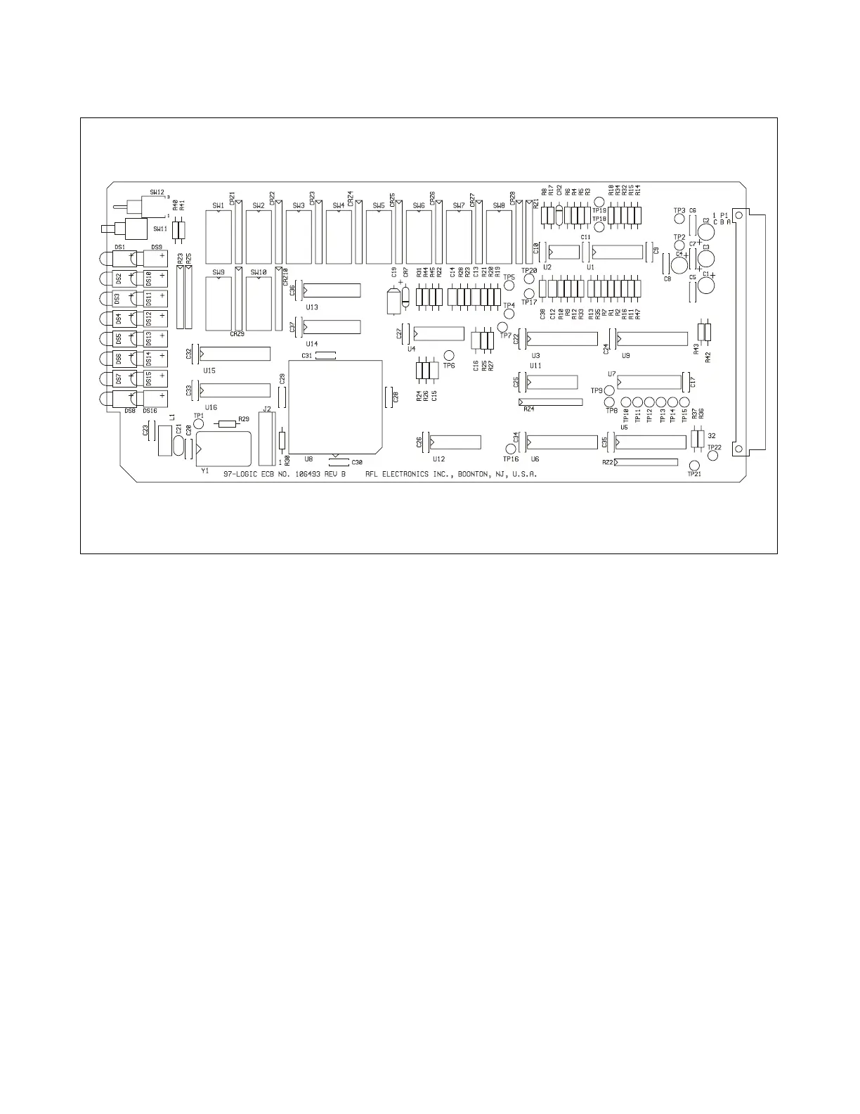
Figure 6-1. RFL 9780 Logic Module
6.1 DESCRIPTION
The RFL 9780 Logic Module interfaces with most of the receiver and transmitter modules within the
system. The Logic module uses guard, trip, and noise input information that it receives from various
parts of the system to build security and dependability into the receiver. In addition, it monitors trip
input signals and generates signals for the Transmitter Module (Section 8) to control frequency shift
and power level. The Logic Module also provides status information for the Sequence of Events
Module (Section 15).
The RFL 9780 Logic Module has eight LED indicator lamps on its front edge which protrude through
the front panel of the RFL 9780. These include GUARD OUT , TRIP OUT, HI SIGNAL, LO SIGNAL,
LOGIC ALARM, TRIP IN 1, TRIP IN 2, and TX FAIL. All LEDs are red with the exception of
GUARD OUT, which is green.
Open-collector transistors are provided on the RFL 9780 Logic Module to drive relays with guard, trip,
logic alarm, and transmitter fail alarm output signals.