RFL 9780 RFL Electronics Inc.
April 8, 2003 4-3 (973) 334-3100
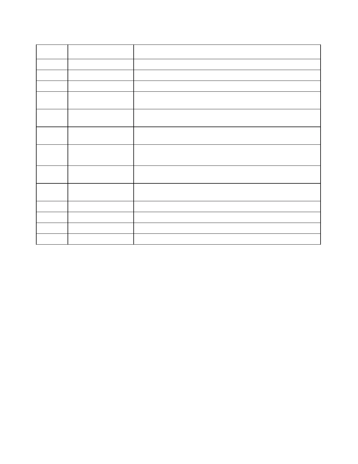
Table 4-1. Controls and indicators, RFL 9780 Front Panel
Item
Number
Name/
Description
Function
1 POWER ON indicator Lights green when system power is ON and the supply is operating properly
2 LO SIG indicator Lights red to indicate an extreme low-level signal condition
3 HI SIG indicator Lights red to indicate an extreme high-level signal condition
4 TRIP OUT indicator Lights red to indicate that a valid trip input has been received and a trip
output has been generated.
5 GUARD OUT indicator Lights green to indicate that a valid guard input has been received and a
guard output has been generated.
6 TRIP RESET
pushbutton
When the trip latch option is enabled, this switch is used to unlatch the TRIP
IN 1, TRIP IN 2, and TRIP OUT LEDs, and de-energize the trip sent relay.
7 RECEIVE LEVEL
display
Displays the power level of the received carrier signal in dB. The range is
–10 dB to +10 dB.
8 SOE RS-232 connector Allows a user to view the SOE log using a dumb terminal or a PC with
terminal emulation software. (See Section 16)
9 LOGIC ALM indicator Lights red to indicate that an abnormal condition has been detected by the
receiver logic.
10 TRIP IN 1 indicator Lights red to indicate that solid state input #1 has been keyed.
11 TRIP IN 2 indicator Lights red to indicate that solid state input #2 has been keyed.
12 TX FAIL indicator Lights red to indicate that the transmitter has failed.
13 LO LEVEL indicator Lights red to indicate that a low level signal is being received.