RFL 9780 RFL Electronics Inc.
April 8, 2003 2-9 (973) 334-3100
Table 2-1. Minimum permissible channel spacings and delay time,
RFL 9780 Programmable FSK Powerline Carrier System
Delay Times* Unidirectional Bidirectional
Frequency
Shift
Nominal
Bandwidth
Normal High Security Channel
Spacing
Channel
Spacing
100 Hz 200 Hz 12 ms 20 ms 500 Hz 1000 Hz
250 Hz 500 Hz 7 ms 15 ms 1250 Hz 2500 Hz
500 Hz 1000 Hz 5 ms 13 ms 2500 Hz 5000 Hz
* Selected by switches on the 9780 Logic Module. The High security setting provides a ten-fold
increase in security, when tested per ANSI C93.5-1997.
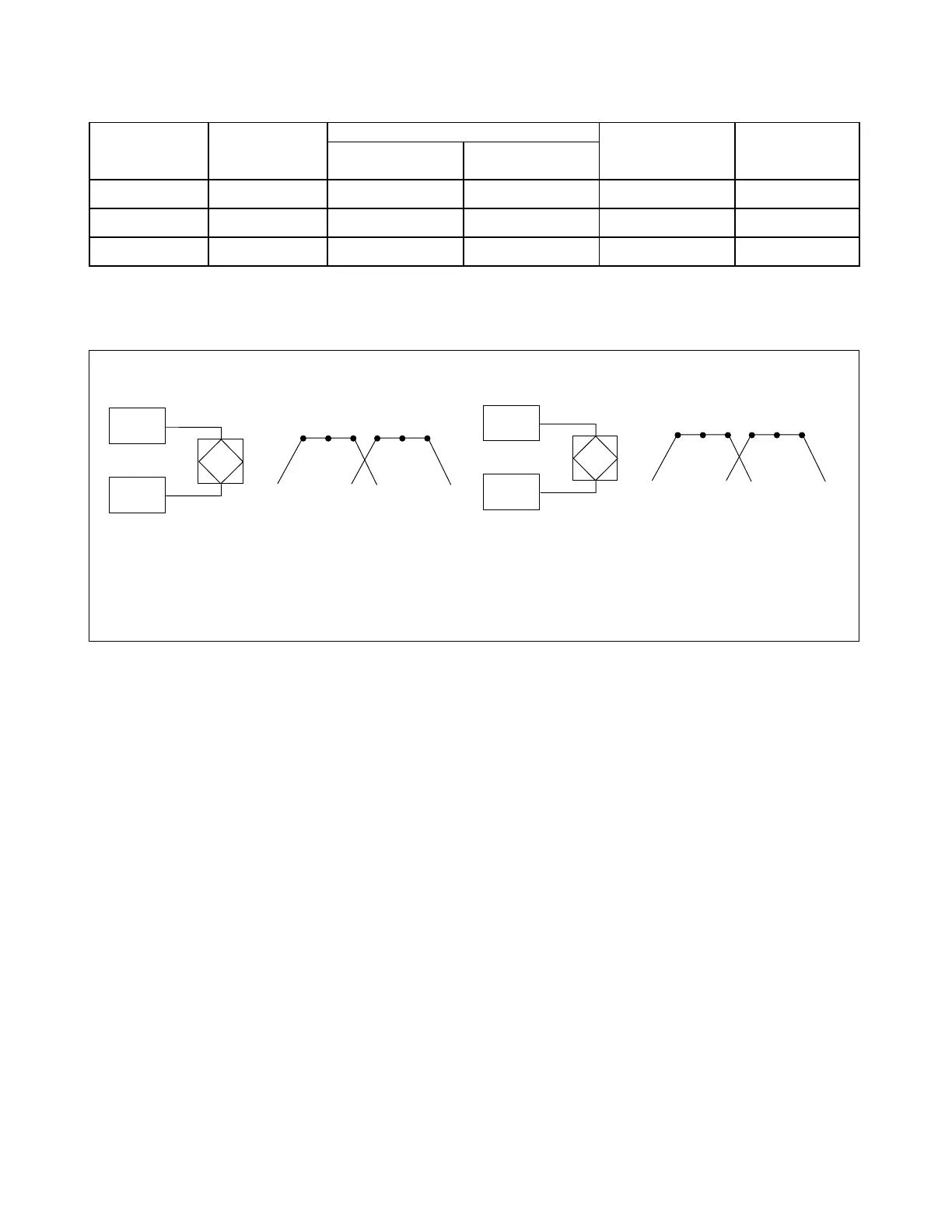
a. Unidirectional system b. Bidirectional system
(500-Hz minimum spacing, 100 Hz shift) (1000-Hz minimum spacing, 100 Hz shift)
Figure 2-2. Typical channel spacings RFL 9780 Programmable FSK Powerline Carrier System
2.7 TERMINAL CONFIGURATION
The RFL 9870 is housed in a single 3U high rack mounted chassis. Depending upon options and the
configuration selected, an expansion chassis may be required, bringing the height to 6U. Table 2-2
shows general information about the available modules for the RFL 9780. Figures 2-3, 2-4 and 2-5
show block diagrams of the Tx/Rx, Tx/Tx and Rx/Rx terminal configurations. A summary of each
module is included in paragraphs 2.8.1 through 2.8.12. Detailed descriptions of the modules can be
found in Sections 6 through 20.
2.8 RFL 9780 SUBASSEMBLIES
Each RFL 9780 terminal contains several circuit board modules and I/O modules. Paragraphs 2.8.1
through 2.8.12 describe the different modules used in the RFL 9780 terminal.
TX
TX
T CF G
CH1 TX
G CF T
CH2 TX
244.9 245.0 245.1 245.4 245.5 245.6
KHz KHz
RESISTIVE HYBRID
TX
RX
T CF G
CH1 TX
G CF T
CH1 RX
244.9 245.0 245.1 245.9 246.0 246.1
KHz KHz
RF SKEWED HYBRID