RFL 9780 RFL Electronics Inc.
April 8, 2003 17-39 (973) 334-3100
17.5 DUAL RELAY I/O MODULE
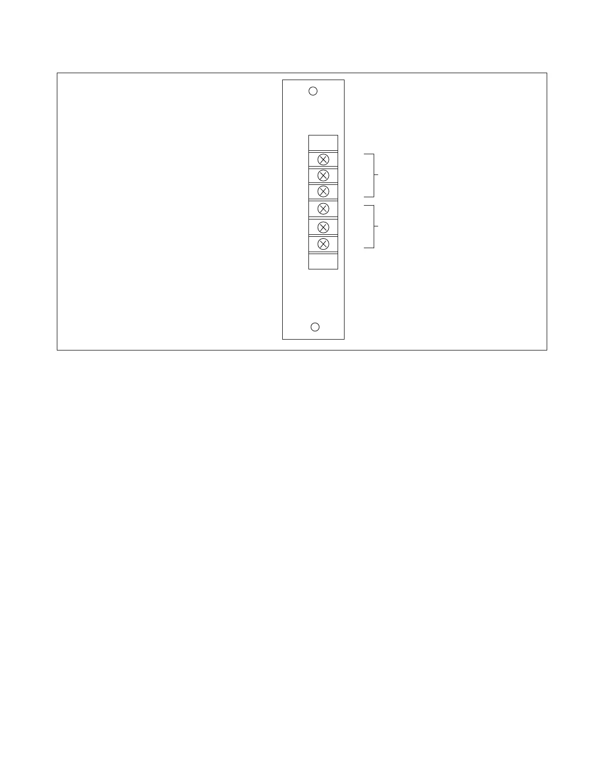
Figure 17-16. Dual Relay I/O module, rear panel view
17.5.1 DESCRIPTION
The Dual Relay I/O module provides two electro-mechanical relay outputs. The outputs are used for
receiving trip and guard commands. The electro-mechanical outputs of each have N.O and N.C.
connections at the terminal block. All signals to and from the Dual Relay I/O module interface directly
with the 9780 Logic Module.
The Dual Relay I/O module requires that jumpers J1, J2 and J3 be configured. Normally J2 and J3 are
installed in the “A” position, and J1 is not installed. Other combinations of these jumpers are not
presently defined.
The Dual Relay I/O module is primarily used for TX/RX, RX/RX and RX only applications. It can also
be used for customer specific applications and can be mounted in a spare I/O slot, if available, or in an
expansion chassis.
17.5.2 CONTROLS AND INDICATORS
Figure 17-17 shows the location of all controls and indicators on the Dual Relay I/O module. These
controls and indicators are described in Table 17-10 Only TB1 is accessible with the Dual Relay I/O
module installed in the chassis. Jumpers J1, J2 and J3 are only accessible when the module is removed
from the chassis or is on a card extender.
DUAL RELAY
OUT 1
C 1
NO 2
NC 3
C 4
NO 5
NC 6
OUT 2
C
NO GUARD OUT
NC
C
NO TRIP OUT
NC