RFL 9780 RFL Electronics Inc.
April 8, 2003 10-1 (973) 334-3100
SECTION 10. OUTPUT FILTER MODULES
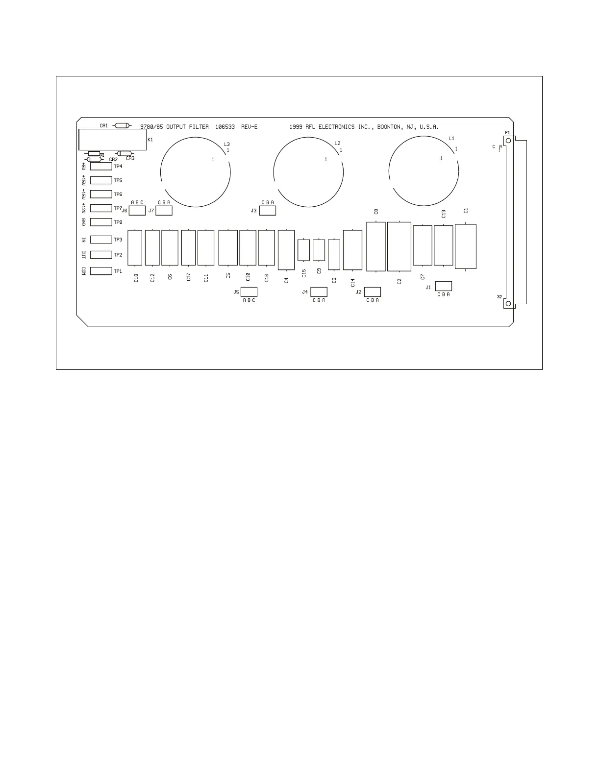
Figure 10-1. Typical RFL 9780 Output Filter Module (without reflected power meter option)
10.1 DESCRIPTION
RFL 9780 Output Filter Modules are used to reduce the harmonic content of the RFL 9780's output
signal to a level that is at least 55 dB below the carrier level. A typical RFL 9780 Output Filter Module
appears in Figure 10-1.
The filters are entirely passive and require no input power for operation. The filters are located after the
power amplifier and are designed to pass the rated full power of 10 watts. Due to the physical size of
some of the components used and the required value changes over the selectable frequency ranges of
the RFL 9780, several filter modules are required.
Color-coded test points are located on the front edge of the module to monitor power supply voltages as
follows: TP4 (red) +5Vdc, TP5 (orange) +15Vdc, TP6 (yellow) –15Vdc, TP7 (purple) +12Vdc, TP8
(black) ground.
Output Filter Modules 106530-11 through -15 have additional circuitry to sense the impedance
mismatch to the load (reflected power). The reflected power can be read locally or remotely using RFL
Web Commander or Hyper-terminal.