RFL 9780 RFL Electronics Inc.
April 8, 2003 6-6 (973) 334-3100
6.4 CONTROLS AND INDICATORS
Figure 6-2 shows the location of all controls and indicators on the RFL 9780 Logic Module. These
controls and indicators are described in Table 6-4. Some of the controls and indicators are accessible
when the module is installed in the chassis and others are accessible only when the module is removed
from the chassis or is on a card extender.
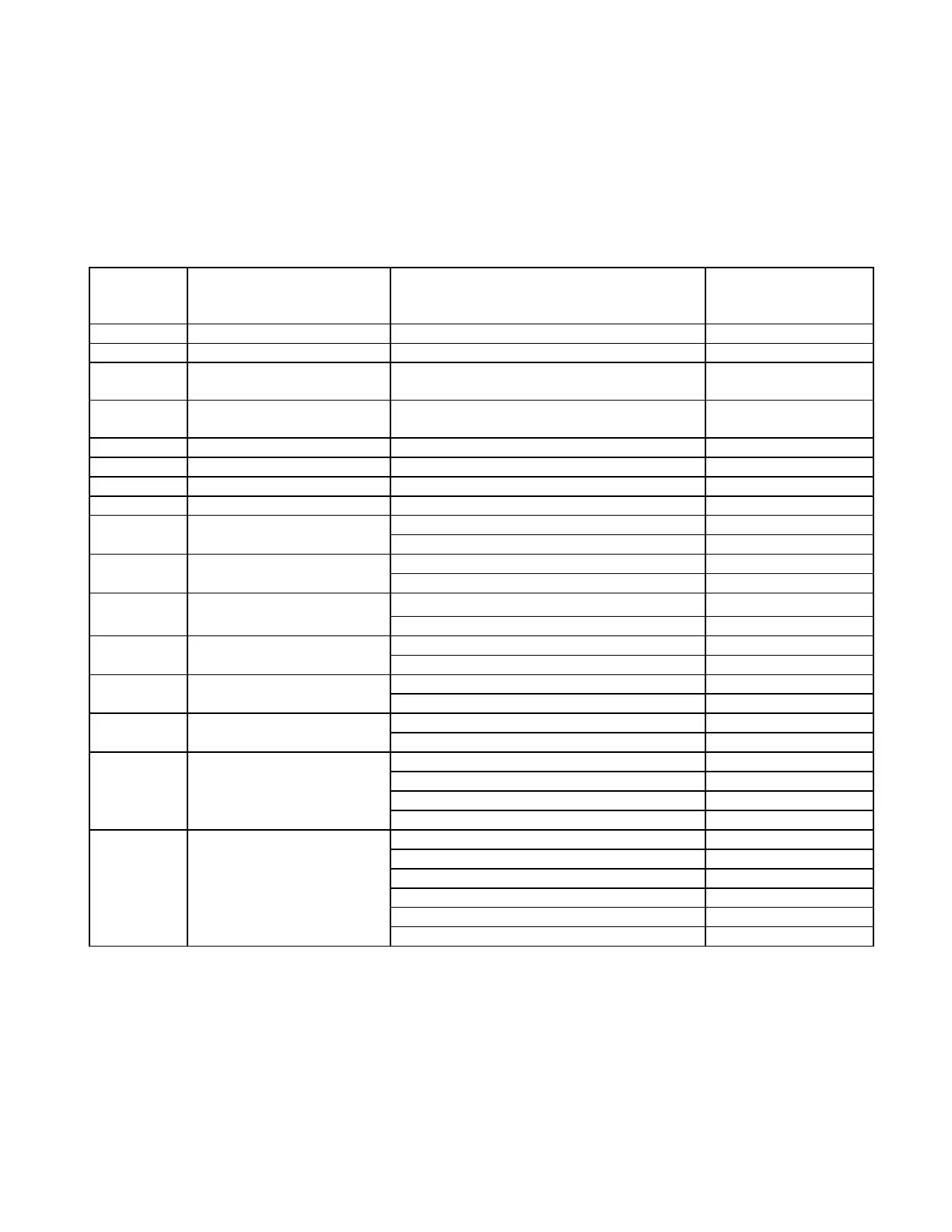
Table 6-4. Controls and indicators, RFL 9780 Logic Module
Component
Designator
Name/Description Function For more information
See paragraph:
DS1 LED Indicator (Guard Out) Lights when valid guard is received. NA
DS2 LED Indicator (Trip Out) Lights when valid trip is received NA
DS3 LED Indicator (High Signal) Lights when higher than nominal level are
received.
NA
DS4 LED Indicator (Low Signal) Lights when lower than nominal level are
received.
NA
DS5 LED Indicator (Logic Alarm) Lights when logic alarm condition exists. NA
DS6 LED Indicator (Trip Input 1) Lights when trip key input 1 is active. NA
DS7 LED Indicator (Trip Input 2) Lights when trip key input 2 is active. NA
DS8 LED Indicator (Tx Fail) Lights when transmitter failure has occurred. NA
SW1 DIP Switch SW1 (1-3) Bipolar noise detector and timer 6.4.1
SW1 (4-8) Pre-guard timer 6.4.2
SW2 DIP Switch SW2 (1) Trip restore 6.4.3
SW2 (2-8) Pre-trip timer 6.4.4
SW3 DIP Switch SW3 (1-3) Unblock trip window timer 6.4.5
SW3 (4-8) Guard hold timer 6.4.6
SW4 DIP Switch SW4 (1-3) Unblock security timer 6.4.7
SW4 (4-8) Trip hold timer 6.4.8
SW5 DIP Switch SW5 (1-4) Trip after guard timer 6.4.9
SW5 (5-8) Guard before trip timer 6.4.9
SW6 DIP Switch SW6 (1-4) Alarm pick-up timer 6.4.10
SW6 (5-8) Alarm drop-out timer 6.4.10
SW7 DIP Switch SW7 (1) Trip latch (TX and RX) 6.4.11
SW7 (2-5) Power boost level 6.4.12
SW7 (6) Not Used N/A
SW7 (7-8) Keying modes (System type) 6.4.13
SW8 DIP Switch SW8 (1) Carrier Envelope Noise detector 6.4.14
SW8 (2) TX Trip Shift Direction 6.4.15
SW8 (3) Trip 1 polarity 6.4.16
SW8 (4) Trip 2 polarity 6.4.16
SW8 (5) RX Trip Shift Direction 6.4.17
SW8 (6-8) Not Used N/A