RFL 9780 RFL Electronics Inc.
April 8, 2003 6-10 (973) 334-3100
6.4.3 CONFIGURATION OF TRIP RESTORE
The position of switch SW2-1 determines the criteria used to unblock the low-level trip channel when
returning to a normal condition from a low-level condition. When SW2-1 is in the ON position, 50ms
of valid Guard condition is selected. When SW2-1 is OFF, 50ms of clear channel (normal level) is
selected. This configuration is used only if the Unblock Function is enabled.
6.4.4 CONFIGURATION OF PRE-TRIP TIMER
The position of switches SW2-2 through SW2-7 determines the total period of time required to validate
a received TRIP signal. The time period shown in Table 6-7 for each switch position is cumulative. A
switch in the ON position enables its corresponding time period. The selectable timer range is between
0ms and 31.75ms in 0.25ms increments. When all switches are in the OFF position, the TRIP signal
passes through without being qualified.
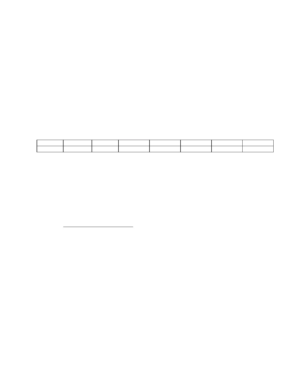
Table 6-7. Configuration of Pre-Trip Timer
Switch SW2-2 SW2-3 SW2-4 SW2-5 SW2-6 SW2-7 SW2-8
Time (ms) 16 8 4 2 1 0.50 0.25
Example: The Pre-trip Timer configured to receive a Trip signal for 5.25ms before being considered to
be a valid Trip would be set as follows:
SW2-2: OFF 0ms
SW2-3: OFF 0ms
SW2-4: ON 4ms
SW2-5: OFF 0ms
SW2-6: ON 1ms
SW2-7: OFF 0ms
SW2-8: ON 0.25ms
TOTAL 5.25ms