RFL 9780 RFL Electronics Inc.
April 8, 2003 15-14 (973) 334-3100
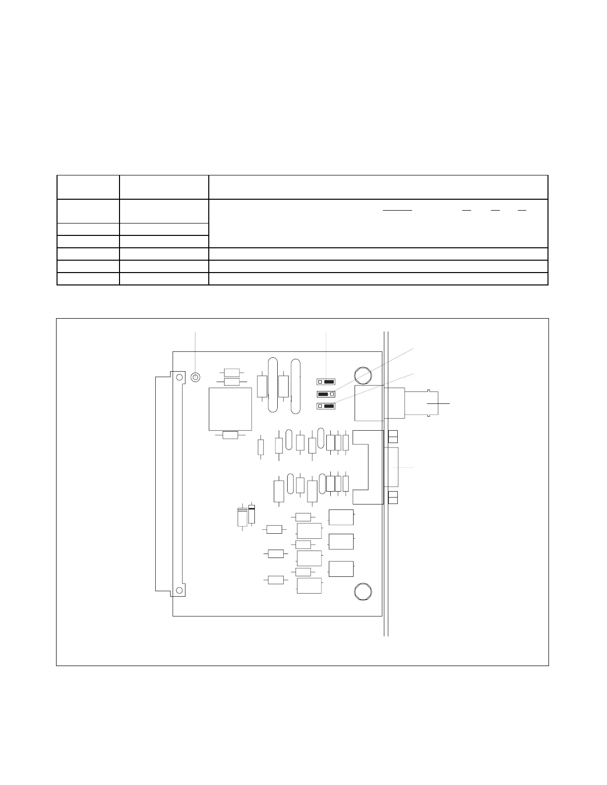
15.3.2 CONTROLS AND INDICATORS
Figure 15-6 shows the location of all jumpers, test points and connectors on the RFL 9780 SOE/IRIG-B
I/O module. The functions of these jumpers, test points and connectors are described in Table 15-4. All
of these items are accessible only when the module is removed from the chassis or is on a card
extender.
Table 15-4. Controls and indicators for the RFL 9780 SOE/IRIG-B I/O Module
Component
Designator
Name/Description Function
J1 Jumper INPUT J1 J2 J3
J2 Jumper Select TTL or bipolar inputs. Demodulated (TTL) OUT OUT OUT
J3 Jumper Modulated (bipolar) IN IN IN
J4 Connector IRIG-B input
P2 Connector RS-232 connection
TP1 Test Point Signal common
TB1
E6
C
6
C
2
C
5
E5
E4
E3
E2
J1
J3
R
1
R
5
R
2
R
3
C
R
6
C
R
9
C
R
4
CR8
CR7
C
R
1
C
9
C12
C13
C14
C15
C16
C10
C
4
C
1
C
7
T1
C
R
5
C
3
C17
C
R
1
0
E1
J4
J2
P2
R
4
TP1
P1
C
R
3
C
R
2
C
1
1
C
8
OUT
OUT
OUT
IN
IN
IN
6
9
5
1
.
0
0
2
u
F
.
0
0
2
u
F
.
0
0
1
u
F
2
2
1
1
0
0
2
2
1
2
2
1
4
0
0
C
A
1
.
5
K
E
4
0
0
C
A
1
.
5
K
E
P
6
K
E
1
6
C
A
16CA
P6KE
16CA
P6KE
P
6
K
E
3
0
C
A
1
K
V
.
0
0
6
8
u
F
.01uF
.
0
0
2
u
F
.
0
0
1
u
F
.
0
0
1
u
F
X
F
M
R
P
1
2
0
0
(
9
5
5
9
5
)
P
6
K
E
6
.
8
.
0
0
1
u
F
S
B
1
6
0
101691
1
0
1
1
0
6
2
2
1
1
6
C
A
P
6
K
E
3
0
C
A
P
6
K
E
1
K
V
.
0
0
6
8
u
F
.
0
0
2
u
F
.01uF
.01uF
103312
103312
103312
103312
103312
103312
.01uF
.01uF
.01uF
.01uF
P2
J1
J2
J
Figure 15-6. Controls and indicators for the RFL 9780 SOE/IRIG-B I/O Module