RFL 9780 RFL Electronics Inc.
March 10, 2000 3-2 (973) 334-3100
1. If the equipment is crated, carefully open the crate to avoid damaging the equipment.
2. Remove the equipment from the crate and carefully examine all packing materials to make sure
no items of value are discarded.
3. Carefully remove any packing materials that were inserted into the individual chassis to hold
circuit cards in place during transit.
3.3 MOUNTING
After unpacking, RFL 9780 equipment must be securely mounted, following the instructions in
paragraphs 3.3.1 through 3.3.3.
3.3.1 INDIVIDUAL CHASSIS
RFL 9780 terminals housed in individual chassis have two mounting ears (one on each side). Hole sizes
and spacings conform to EIA standards, so the RFL 9780 can be mounted in any standard 19-inch rack
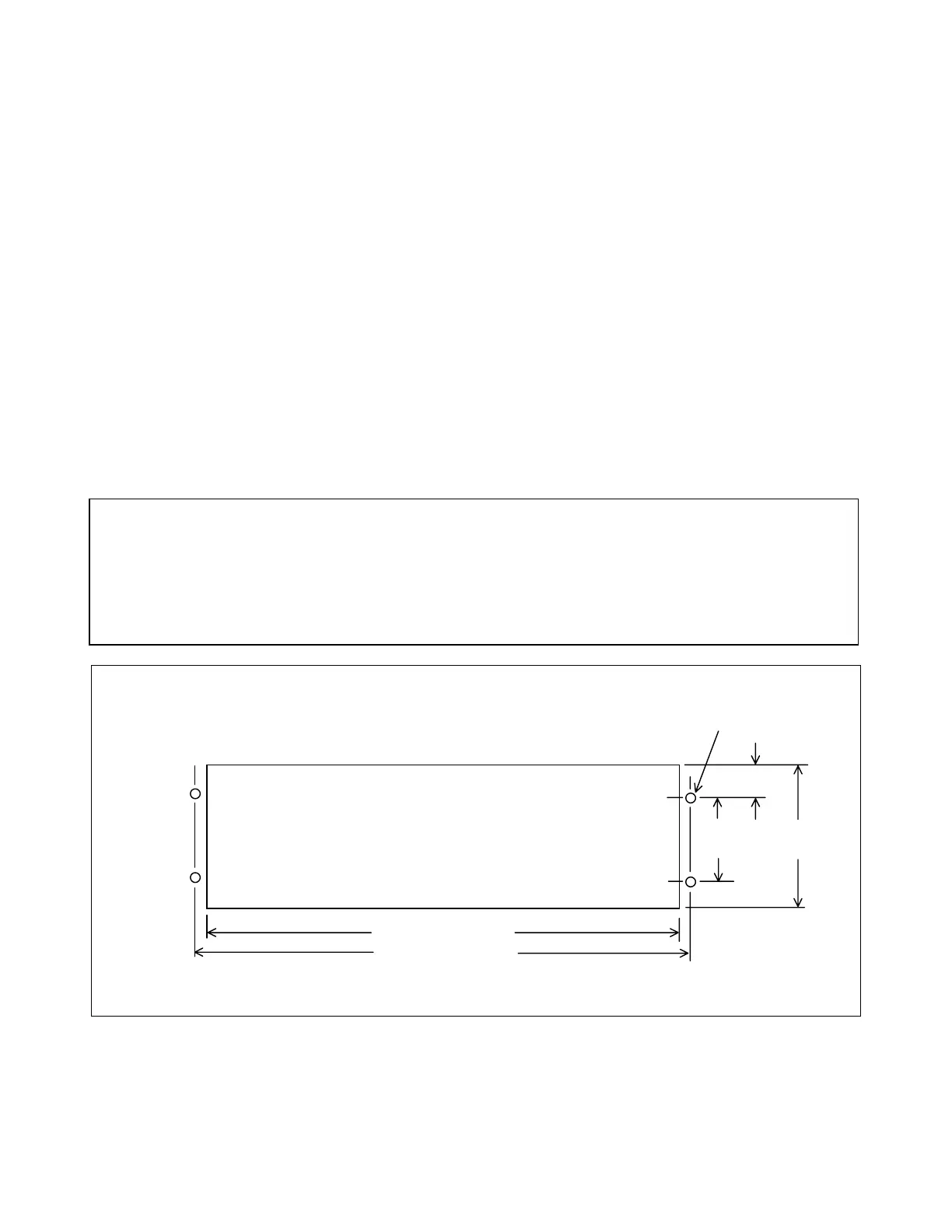
or cabinet. Complete chassis dimensions are shown in Figure 3-1.
CAUTION
ANY INSTALLATION USING AN ENCLOSED CABINET WITH A SWING-OUT RACK
MUST BE SECURELY FASTENED TO THE FLOOR. THIS WILL PREVENT THE
CABINET FROM FALLING FORWARD WHEN THE RACK IS MOVED OUTWARD
Figure 3-1. Mounting dimensions, RFL 9780 Programmable FSK Powerline Carrier System
0.187 in. (0.475 cm.) DIA.
(4) REQ.
2.25 in. 5.25 in.
(5.715 cm.) (13.335 cm.)
1.5 in.
(3.81 cm.)
CUTOUT
17.625 in. (44.768 cm.
18.312 in. (46.512 cm)