RFL 9780 RFL Electronics Inc.
April 8, 2003 10-4 (973) 334-3100
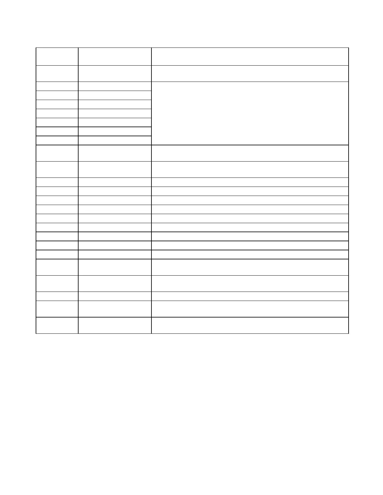
Table 10-1. Controls and indicators, RFL 9780 Output Filter Modules
Component
Designator
Name/
Description
Function
C26 Trimmer capacitor Adjusts phase of voltage across one of the transformer secondaries. For
factory use only
J1 Jumper
J2 Jumper
J3 Jumper Passband frequency select jumpers.
J4 Jumper See Table 10-2, and Figures 10-2 and 10-3
J5 Jumper
J6 Jumper
J7 Jumper
R8 Potentiometer Adjusts circuit gain and calibrates the signal level measurement (VA) for a
given transmitter output power level. For factory use only.
R9 Potentiometer Adjusts amplitude of voltage across one of the transformer secondaries. For
factory use only.
R42 Potentiometer Calibration attenuator. For factory use only.
TP1 Test point Filter common
TP2 Test point Filter output
TP3 Test point Filter input
TP4 Power supply test point + 5 Vdc
TP5 Power supply test point + 15 Vdc
TP6 Power supply test point - 15 Vdc
TP7 Power supply test point + 12 Vdc
TP8 Power supply test point Power supply common
TP9 Test point DC signal, which represents the nominal transmitter signal level. For
factory use only
TP10 Test point DC signal VAMP. Represents the voltage equivalent of the nominal
transmitter signal amplitude. For factory use only.
TP11 Test point Reflected power measurement signal. For factory use only.
TP12 Test point DC signal QVRP (quadrature component of the reflection coefficient) For
factory use only
TP13 Test point DC signal IVRP(in-phase component of the reflection coefficient) For
factory use only.