RFL 9780 RFL Electronics Inc.
April 8, 2003 6-9 (973) 334-3100
6.4.1 CONFIGURATION OF BI-POLAR NOISE DETECTOR
The position of switches SW1-1 through SW1-3 determines the total period of time that the Pre-trip
timer is extended when bi-polar noise is detected. The time period shown in Table 6-5 for each switch
position is cumulative. A switch in the ON position enables its corresponding time period. The
selectable timer range is between 2ms and 14ms in 2ms increments.
NOTE: When all switches are in the OFF position, the Bi-polar Noise Detector is disabled.
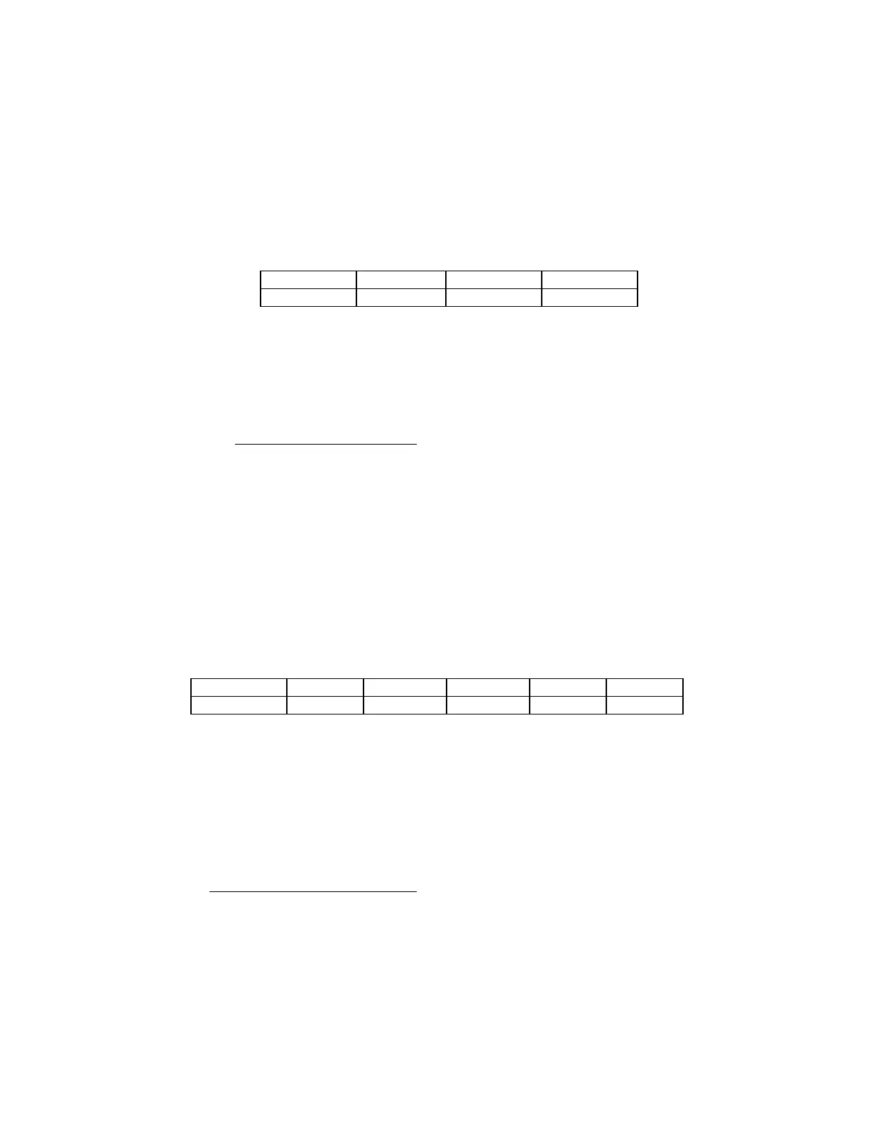
Table 6-5. Configuration of Bi-Polar Noise Detector
Switch SW1-1 SW1-2 SW1-3
Time (ms) 8 4 2
Example: The Bi-polar Noise Detector configured to extend the Pre-trip timer for an additional period
of 12ms would be set as follows:
SW1-1: ON 8ms
SW1-2: ON 4ms
SW1-3: OFF 0ms
TOTAL 12ms
6.4.2 CONFIGURATION OF PRE-GUARD TIMER
The position of switches SW1-4 through SW1-8 determines the total period of time required to validate
a received Guard signal. The time period shown in Table 6-6 for each switch position is cumulative. A
switch in the ON position enables its corresponding time period. The selectable timer range is between
0ms and 31ms in 1ms increments. When all switches are in the OFF position, the Guard signal passes
through without being qualified.
Table 6-6. Configuration of Pre-Guard Timer
Switch SW1-4 SW1-5 SW1-6 SW1-7 SW1-8
Time (ms) 16 8 4 2 1
Example: The Pre-guard Timer configured to receive a Guard signal for 12ms before being considered
to be a valid Guard would be set as follows:
SW1-4: OFF 0ms
SW1-5: ON 8ms
SW1-6: ON 4ms
SW1-7: OFF 0ms
SW1-8: OFF 0ms
TOTAL 12ms