RFL 9780 RFL Electronics Inc.
April 8, 2003 13-3 (973) 334-3100
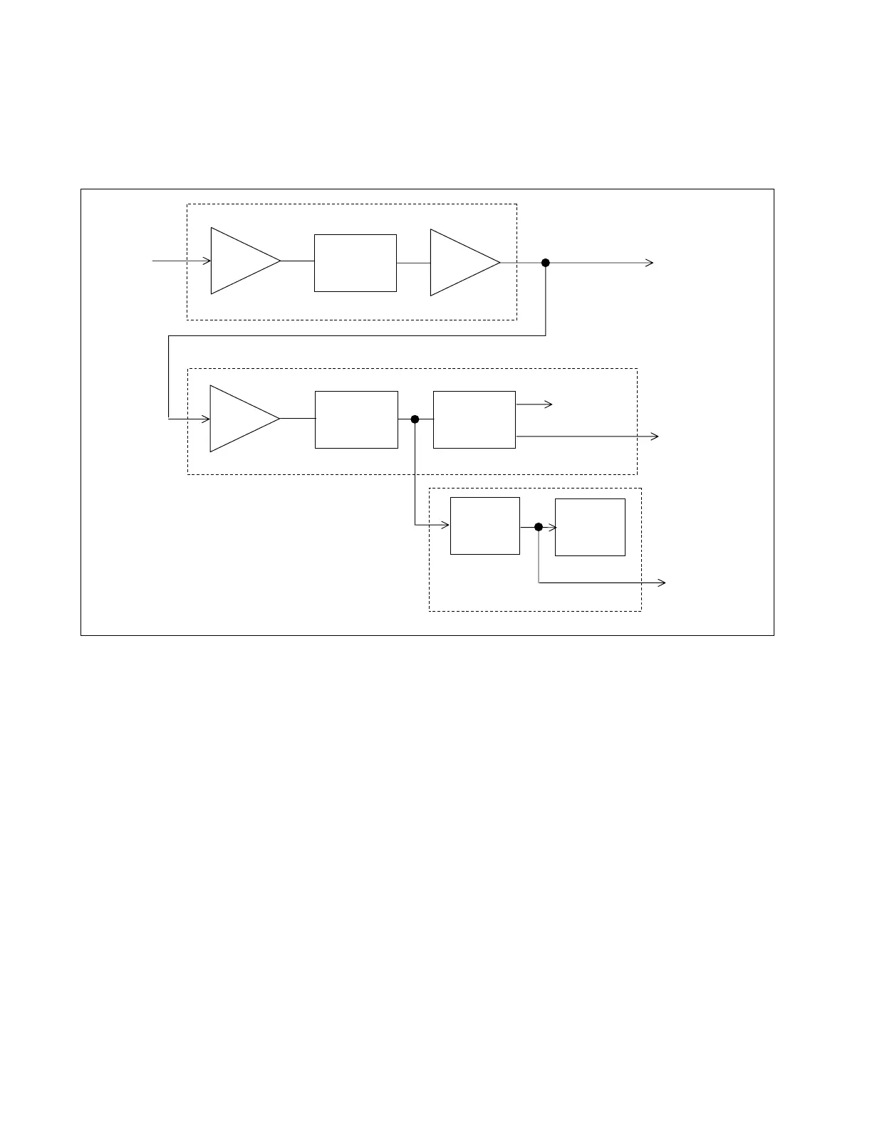
13.3 THEORY OF OPERATION
The RFL 9780 CLI module contains a narrowband filter, a signal monitoring circuit, and a carrier level
indicator. A block diagram of the RFL 9780 CLI module appears in Figure 13-2 and its schematic appears
in Figure 13-5.
Figure 13-2. Block diagram, RFL 9780 Carrier Level Indicator Module
13.3.1 NARROWBAND FILTER
The output signal from the RFL 9780 IF/BF module (Section 12) enters the RFL 9780 CLI module at
edge connector terminal C13. It is then applied to operational amplifier U8A, which serves as an input
buffer. From there, it passes to an active narrowband filter, formed from quad operational amplifiers U2
and U3, and their associated components.
The 106485-4 module has a 200Hz bandwidth (BW) filter and is used in ±100 Hz shift systems. The
106485-5 and 106485-6 modules have 500 Hz and 1000Hz BW filters for ±250 and ± 500 Hz shift
systems respectively.
The output of the filter is buffered by operational amplifier U7A. FILT LEVEL potentiometer R73
varies the gain of U7A, which controls the amplitude of the 4kHz OUT signal at edge connector
terminal A18.
INPUT
BUFFER
FILTER
BUFFER
BUFFER
PRECISION
RECTIFIER
COMPARATOR
METER
DRIVE
CIRCUIT
DIGITAL
PANEL
METER
TO DS1
LOW LEVEL
LED
4 KHZ OUT
TO
LARM
RELAY
TO
EXTERNAL
METER
(OPTIONAL)
4 KHZ
FROM
IF/BF
MODULE
NARROWBAND
SIGNAL LEVEL MONITOR
CARRIER LEVEL INDICATOR