RFL 9780 RFL Electronics Inc.
April 8, 2003 13-5 (973) 334-3100
When an external 0 to -5 Vdc meter is used, jumper J1 must be in the “C” position. This sends the
output of the log amplifier (U5B) directly to pin C16. The external meter return is connected to pin
C17. Zero Vdc corresponds to -10.0 dB, -2.5 Vdc corresponds to 0 dB, and -5 Vdc corresponds to +10
dB.
13.4 CONTROLS AND INDICATORS
Figure 13-3 shows the location of all controls and indicators on the RFL 9780 Carrier Level Indicator
module. These controls and indicators are described in Table 13-1. Only DS1, R30 and R58 are
accessible with the RFL 9780 Carrier Level Indicator Module installed in the chassis. All others are
accessible when the module is removed from the chassis or is on a card extender.
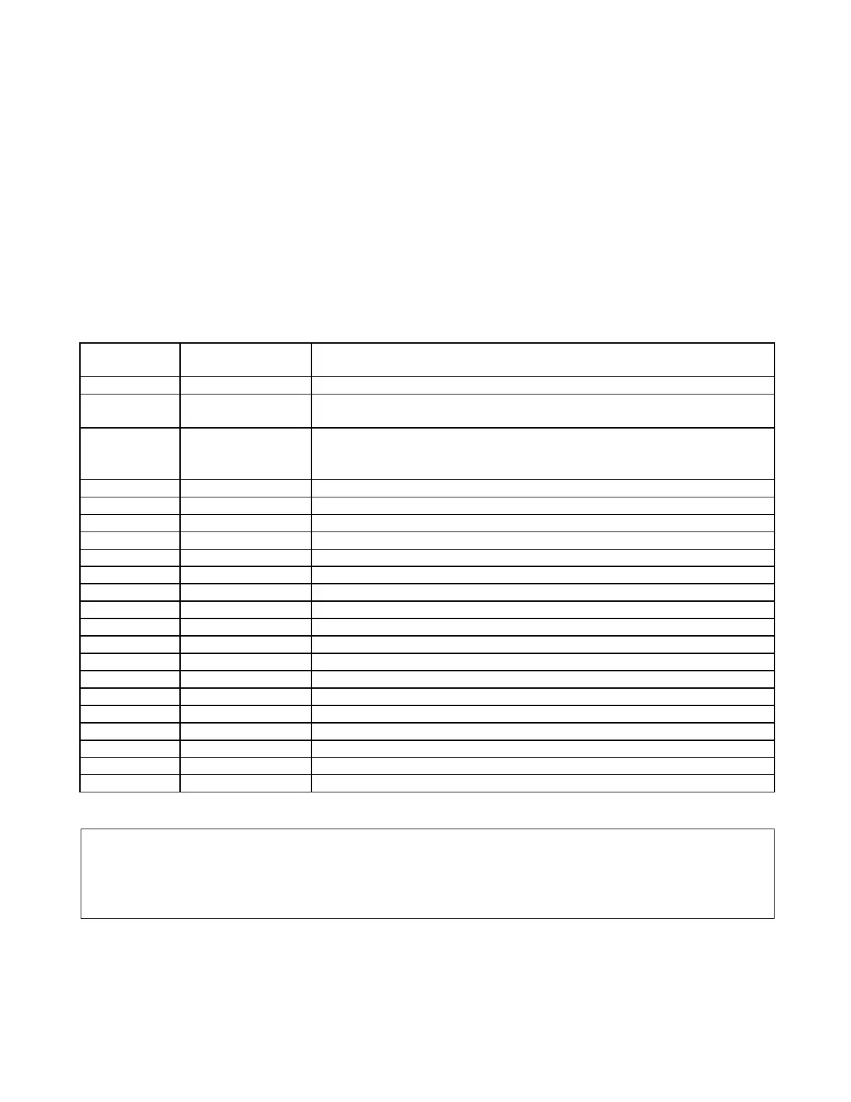
Table 13-1. Controls and indicators, RFL 9780 Carrier Level Indicator
Component
Designator
Name/Description Function
DPM1 Digital Panel Meter Displays signal level in dB.
DS1 Light Emitting
Diode
When lit, indicates that the received level has dropped below a setpoint
J1 Jumper
Position “A” selects ±1 Vdc output.
Position “B” selects 0 to -100µA output.
Position “C” selects 0 to -5 Vdc output.
J2 3 Position Jumper Used to scale the digital level meter for 1W, 3W or 10W operation
R11* Potentiometer Narrow Band filter adjust
R17* Potentiometer Narrow Band filter adjust
R23* Potentiometer Narrow Band filter adjust
R30 Potentiometer Sets the signal level meter to zero dB (meter null)
R58 Potentiometer Sets the alarm level alarm threshold
R73 Potentiometer Sets the signal level at the output of the narrow-band filter (output gain)
R76* Potentiometer Calibrates the meter signal
R95 Potentiometer Presently not used
R106* Potentiometer Narrow Band filter adjust
TP1 Test Point (black) Signal ground
TP2 Test Point (orange) Signal after input buffer
TP3 Test Point (orange) Scaled signal prior to level detector circuit
TP4 Test Point (orange) Output of logarithmic amplifier
TP5 Test Point (yellow) Output of signal level detector and filter
TP6 Test Point (orange) Signal applied to Digital Panel Meter
TP7 Test Point (orange) Module output signal
TP8 Test Point (orange) Signal applied to External Meter
*For factory use only.
NOTE
J2 Jumper Chart on Page 13-19 is used for factory alignment only
>> text continues on page 13-7 <<