RFL 9780 RFL Electronics Inc.
October 12, 1999 5-5 (973) 334-3100
The input fuse for RFL 9780 power supply I/O module is located on the rear of the power supply I/O
module. The fuse can be changed without removing the power supply I/O module from the chassis. To
check and/or replace the fuse, proceed as follows:
1. Place the POWER switch on the power supply I/O module to the OFF position.
2. Remove the input fuse from its fuseholder by using a screwdriver and turning it counter
clockwise about 1/4 turn.
3. Remove the fuse from the fuseholder cap and inspect it for damage. If the fuse is bad, it must be
replaced. If the fuse is good, check for the presence of input voltage across TB1-1 and TB1-2 on
the rear panel. If voltage is present and the power supply does not function, troubleshoot the
supply to determine the cause of failure.
4. Insert a fuse with the proper voltage and current ratings into the fuseholder cap and push it in
until it is firmly seated. Using a flat-blade screwdriver, push in on the cap and turn clockwise
about one quarter-turn. This will secure the fuse in place.
For continued safe operation, always replace a fuse with one having the same
voltage and current ratings. Refer to Table 5-1 or Section 19 for proper fuse
replacements.
5. Once the fuse has been checked and/or replaced, place the power switch to the ON position.
If the green power indicator of the front of the power supply lights, the power supply module is
working properly. If the indicator does not light or if the fuse blows again, troubleshoot the
power supply module.
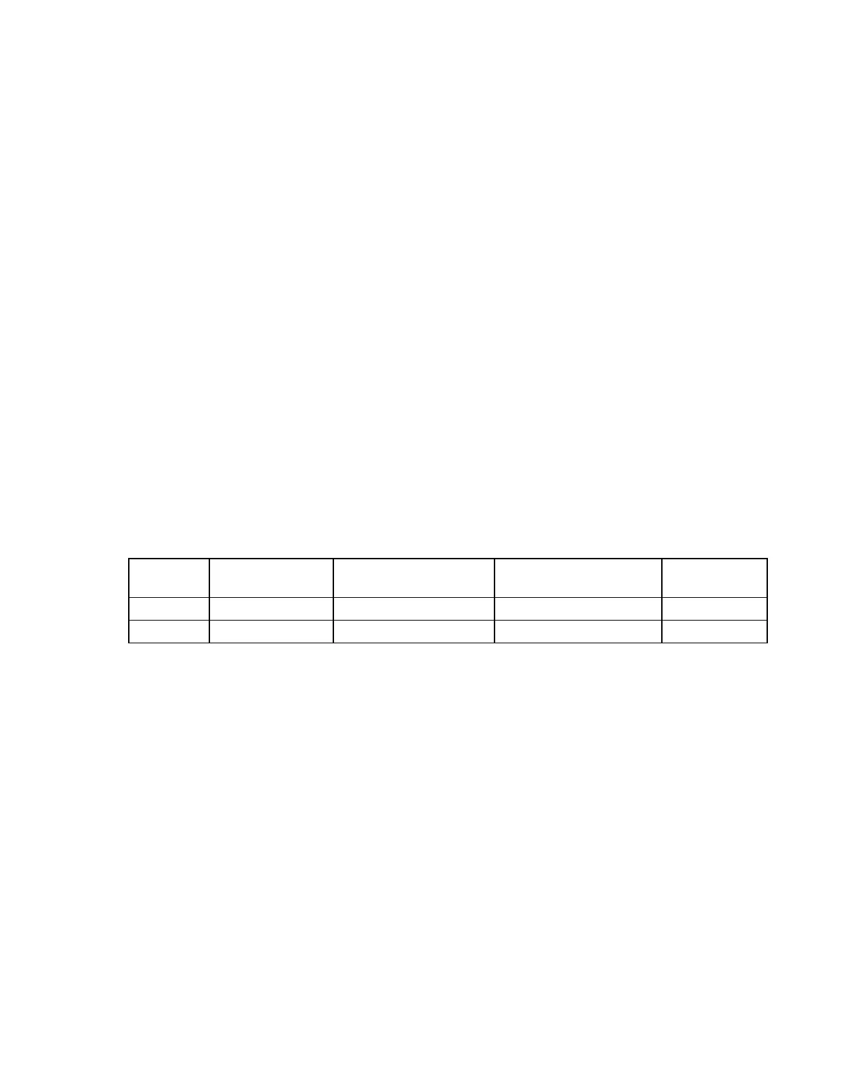
Table 5-1. Fuse replacement data, RFL 9780 power supply I/O module.
Model Assembly
Number
Fuse Rating Manufacturers type Part Number
48/125Vdc 106455-1 3AG, slo-blow, 250V, 4A Littlefuse or equiv. 301122
250Vdc 106455-2 3AG, slo-blow, 250V, 4A Littlefuse or equiv. 301122
5.4 CORRECTIVE MAINTENANCE
The RFL 9780 Programmable FSK Powerline Carrier System has been designed for years of trouble-
free service. Should a malfunction occur involving the RFL 9780, use standard troubleshooting
techniques to determine if the problem is in the RFL 9780, or in some other connected equipment. If the
problem lies within the RFL 9780, use the schematics at the end of Sections 6 through 18 to try and
determine which module is defective. Once this is done, replace the module; this should solve the
problem.
Defective modules can be repaired locally, or they can be returned to RFL for repair (para 5.6).
5.5 HOW TO ARRANGE FOR SERVICING
If necessary, RFL 9780 modules and subassemblies may be returned to RFL for repair. Contact our
Customer Service Department using the telephone number listed below. You will be given a Returned
Material Authorization (RMA) and shipping instructions.