RFL 9780 RFL Electronics Inc.
April 8, 2003 6-12 (973) 334-3100
6.4.7 CONFIGURATION OF UNBLOCK SECURITY TIMER
The position of switches SW4-1 through SW4-3 determines the threshold at which a signal is
considered to be at a low-level condition. The time period shown in Table 6-10 for each switch position
is cumulative. A switch in the ON position enables its corresponding time period. The selectable timer
range is between 10ms and 70ms. NOTE: Any combination of switches in the ON position enables
the Unblocking Function. All switches in the OFF position disables the Unblocking Function.
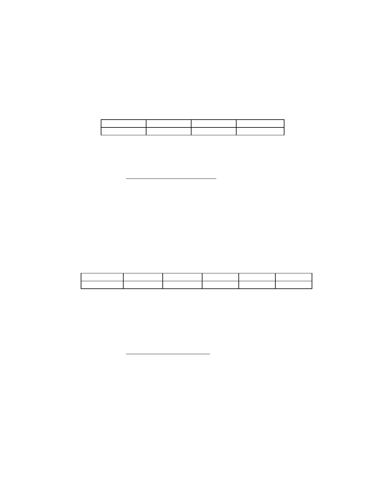
Table 6-10. Configuration of Unblock Security Timer
Switch SW4-1 SW4-2 SW4-3
Time (ms) 40 20 10
Example: The Unblock Security Timer configured for a threshold of 50ms would be set as follows:
SW4-1: ON 40ms
SW4-2: OFF 0ms
SW4-3: ON 10ms
TOTAL 50ms
6.4.8 CONFIGURATION OF TRIP HOLD TIMER
The position of switches SW4-4 through SW4-8 determines the minimum period of time a Trip will be
held once a valid Trip has been established. The time period shown in Table 6-11 for each switch
position is cumulative. A switch in the ON position enables its corresponding time period. The
selectable timer range is between 0ms and 310ms in increments of 10ms. When all switches are in the
OFF position, the Trip signal is not held.
Table 6-11. Configuration of Trip Hold Timer
Switch SW4-4 SW4-5 SW4-6 SW4-7 SW4-8
Time (ms) 160 80 40 20 10
Example: The Trip Hold Timer configured to hold a valid Trip signal for a minimum of 130ms would
be set as follows:
SW4-4: OFF 0ms
SW4-5: ON 80ms
SW4-6: ON 40ms
SW4-7: OFF 0ms
SW4-8: ON 10ms
TOTAL 130ms