RFL 9780 RFL Electronics Inc.
April 8, 2003 17-6 (973) 334-3100
17.2.2 CONTROLS AND INDICATORS
Figure 17-4 shows the location of all controls and indicators on the Solid State Relay I/O module.
These controls and indicators are described in Table 17-2. Only TB1 is accessible with the Solid State
Relay I/O module installed in the chassis. Jumpers J4 and J5 are accessible only when the module is
removed from the chassis or is on a card extender.
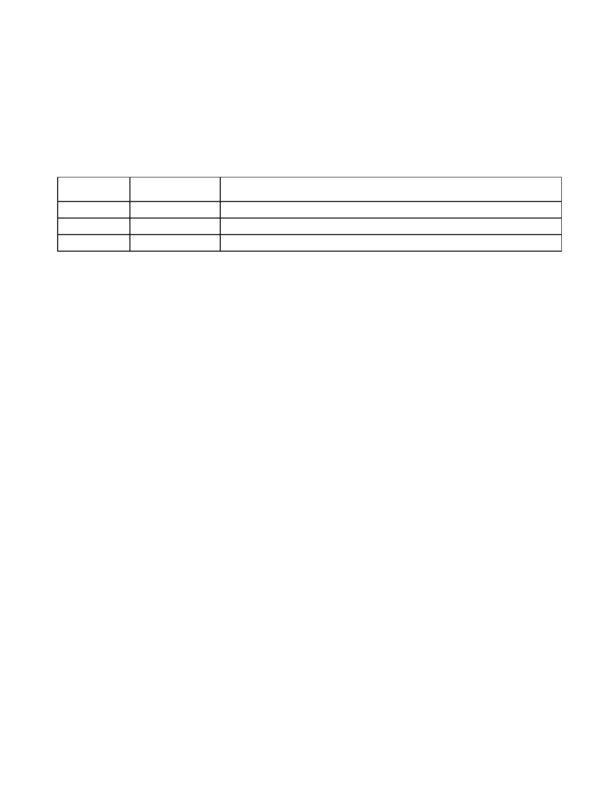
Table 17-2. Controls and indicators, Solid State Relay I/O module
Component
Designator
Name/
Description
Function
J4 Jumper Selects 48V or 125V operation (not installed for 250V version)
J5 Jumper Selects 48V or 125V operation (not installed for 250V version)
TB1 Terminal block Provides connections to line coupling equipment.