RFL 9780 RFL Electronics Inc.
April 8, 2003 6-15 (973) 334-3100
6.4.12 CONFIGURATION OF POWER-BOOST LEVELS
The position of switches SW7-2 through SW7-5 determines the boost modes for 2F and 3F systems for
each of the following conditions: Guard, TRIPIN_1 keyed, and TRIPIN_2 keyed. See Table 6-11 for
configuration of Power-boost levels. Refer to the Keying Modes in Table 6-14 to determine the state of
the system when TRIPIN_1 and/or TRIPIN_2 are keyed for the mode in which the system is being
configured.
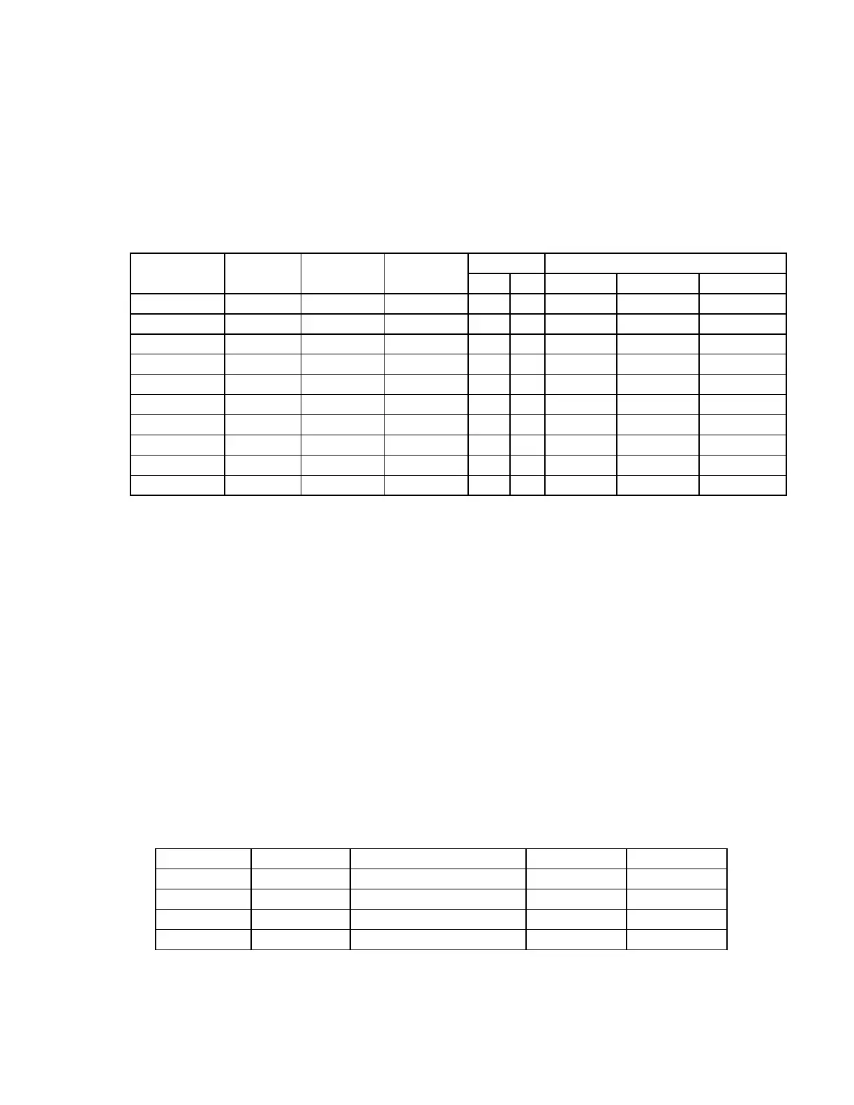
Table 6-14. Configuration of Power Boost Levels
SW7-4 SW7-5 MODE POWER BOOST LEVELSSW7 -2 SW7-3
2F 3F GUARD TRIPIN_1 TRIPIN_2
OFF OFF OFF OFF X 1W 1W 1W*
OFF OFF ON OFF X 1W 10W 1W*
OFF ON OFF ON X 3W 10W 10W
OFF ON OFF OFF X 10W 10W 10W*
OFF ON ON OFF X 1W 1W 1W
ON OFF OFF OFF X 1W 10W 1W
ON OFF ON OFF X 1W 1W 10W
ON ON OFF OFF X 1W 10W 10W
ON ON ON ON X 3W 10W 10W
ON ON ON OFF X 10W 10W 10W
Power Boost levels indicated with an asterisk for TRIPIN_2 for 2F Mode apply to 2F Start/Stop
systems only. TRIPIN_2 (STOP) overrides TRIPIN_1 (START) reducing the power level to the
same as guard power level as indicated in Table 6-11.
6.4.13 CONFIGURATION OF KEYING MODES
The position of switches SW7-7 and SW7-8 determines the Keying Mode of the system. Refer to Table
6-15 for system configuration.
2F Single-Trip Keying: A TRIP is generated when TRIPIN_1 is keyed. TRIPIN_2 is not used.
2F Dual-Trip Keying: A TRIP is generated when TRIPIN_1 and TRIPIN_2 are simultaneously
keyed (TRIPA and TRIPB).
2F Start/Stop Keying: A START is generated when TRIPIN_1 is keyed. A STOP is generated
when TRIPIN_2 is keyed. A STOP overrides a START.
3F Dual-Function: A BLOCK is generated when TRIPIN_1 is keyed. A TRIP is generated
when TRIPIN_2 is keyed. A TRIP has priority over a BLOCK.
Table 6 15. Configuration of Keying Modes
SW7-7 SW7-8 KEYING MODE TRIPIN_1 TRIPIN_2
OFF OFF 2F Single-Trip Keying TRIP N/A
OFF ON 2F Dual-Trip Keying TRIP A TRIP B
ON OFF 2F Start/Stop Keying START STOP
ON ON 3F Dual-Function BLOCK TRIP