RFL 9780 RFL Electronics Inc.
May 19, 2000 9-4 (973) 334-3100
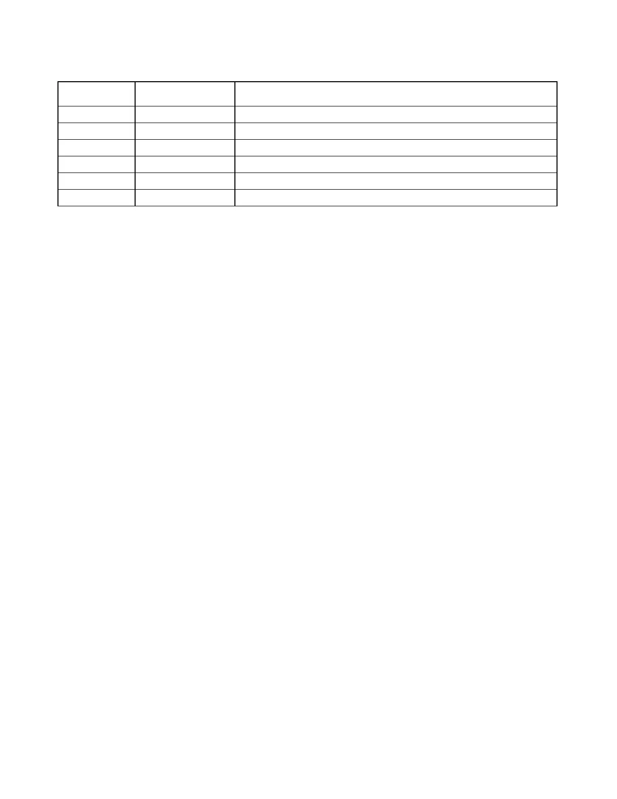
Table 9-1. Controls and indicators, RFL 9780 Power Amplifier Module
Component
Designator
Name/Description Function
R2 Potentiometer Gain adjustment
R10 Potentiometer Tx Fail threshold voltage adjustment
R16 Potentiometer Output impedance adjustment
TP1 Test point Input signal test point
TP2 Test point Operational amplifier (U1) output
TP3 Test point Output signal test point
9.4.1 AMPLIFIER GAIN
The gain potentiometer R2, can be used to vary the output signal level, and thus power. The “Transmit
Amplitude” adjustment on the Transmitter Module can also be used to vary the output level.
9.4.2 OUTPUT IMPEDANCE
There are provisions for adjusting the output impedance of the Power Amplifier Module to compensate
for circuit variations in actual field installations. This only requires adjustment during initial system
installation, or following system changes that impact the impedance the 9780 is driving.
To match the impedance proceed as follows with the system off-line:
1. Set the unit to transmit a 1W or 3W signal . Do not set the unit for a 10W transmit level.
2. Remove the load from the output of the 9780 and measure the output signal voltage.
3. Connect the actual load to the 9780 and adjust potentiometer R16 (impedance adjust) to obtain
one-half of the unloaded output signal level.
9.4.3 LOW-LEVEL ALARM THRESHOLD
The low-level alarm threshold can be set as follows:
1. Set the RFL 9780 to generate the lowest normal output level (10W for a 10W/10W system, 1W
for a 1W/10W system).
2. Using the gain adjust potentiometer R2, lower the transmit level to the desired threshold level
(typically 80% to 90% of nominal).
3. Adjust R10 to trip the Tx Fail output.
4. Readjust R2 to provide the desired output voltage.