RFL 9780 RFL Electronics Inc.
November 1, 2000 7-7 (973) 334-3100
7.4.4 CONFIGURATION OF VOICE ENABLE OPTION
This feature is used with the voice option, which is not being offered at this time. Switch
SW1-5 should be in the OFF position.
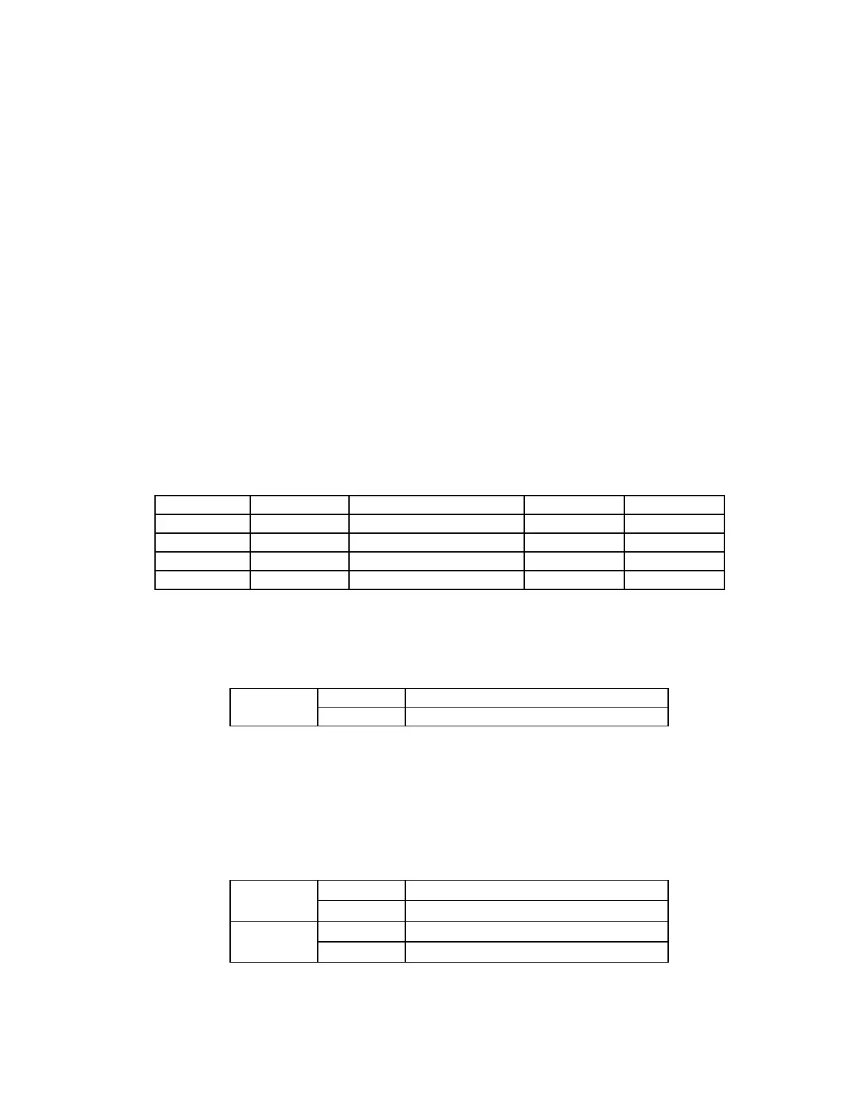
7.4.5 CONFIGURATION OF KEYING MODES
The position of switches SW1-7 and SW1-8 determines the Keying Mode of the system. Refer to Table
7-4 for system configuration.
2F Single-Trip Keying: A TRIP is generated when TRIPIN_1 is keyed. TRIPIN_2 is not used.
2F Dual-Trip Keying: A TRIP is generated when TRIPIN_1 and TRIPIN_2 are simultaneously
keyed (TRIPA and TRIPB).
2F Start/Stop Keying: A START is generated when TRIPIN_1 is keyed. A STOP is generated
when TRIPIN_2 is keyed. A STOP overrides a START.
3F Dual-Function: A BLOCK is generated when TRIPIN_1 is keyed. A TRIP is generated
when TRIPIN_2 is keyed. A TRIP has priority over a BLOCK.
Table 7-4. Configuration Of Keying Modes
SW1-7 SW1-8 KEYING MODE TRIPIN_1 TRIPIN_2
OFF OFF 2F Single-Trip Keying TRIP N/A
OFF ON 2F Dual-Trip Keying TRIP A TRIP B
ON OFF 2F Start/Stop Keying START STOP
ON ON 3F Dual-Function BLOCK TRIP
7.4.6 CONFIGURATION OF TRIP POLARITY
The position of switch SW2-1 determines trip polarity as shown in Table 7-5.
Table 7-5. Trip Polarity
SW2-1 ON Guard = shift down; Trip = shift up
OFF Guard = shift up; Trip = shift down
7.4.7 CONFIGURATION OF TRIPIN_1 AND TRIPIN_2 SOLID-STATE
CONTACTS
The position of switches SW2-2 and SW2-3 determine the solid-state input configuration of Tripin 1
and Tripin 2 as shown in Table 7-6.
Table 7-6. Trip Polarity
SW2-2 ON Tripin 1 is normally energized
OFF Tripin 1 is normally de-energized
SW2-3 ON Tripin 2 is normally energized
OFF Tripin 2 is normally de-energized