RFL 9780 RFL Electronics Inc.
May 19, 2000 9-3 (973) 334-3100
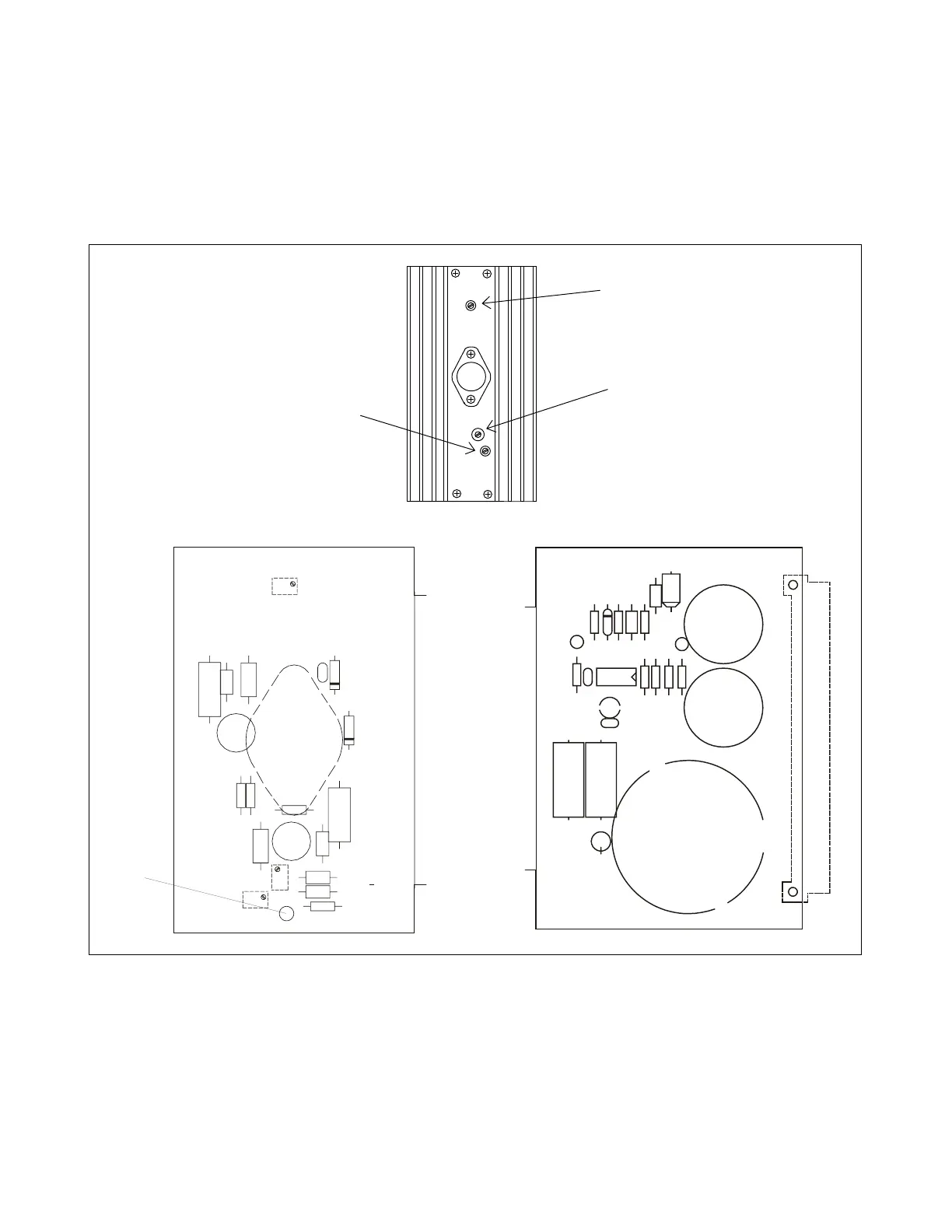
9.4 CONTROLS AND INDICATORS
Figure 9-2 shows the location of all controls and indicators on the RFL 9780 Power Amplifier module.
These controls and indicators are described in Table 9-1. Potentiometers R2, R10 and R16 are
accessible with the RFL 9780 Power Amplifier Module installed in the chassis. Test points TP1, TP2
and TP3 are only accessible when the module is removed from the chassis or is on a card extender.
C15
R17
R16
CR5
R2
CR6
C4
C2
C1
C5
R6
R3
R1
C3
CR3
R10
TP1
U1
CR4
R5
R4
C6
+
+
106463-2 REV-C
1999 RFL ELECTRONICS INC, USA
T1
C16
C17
C9
C14
C10
T1
C8
TP3
TP2
CR7
R18
C11
R15
R14
R13
R9
R8
R11 R12
R7
U2
C7
C12
C13
P1
+
+
+
1
1
+
106463-1 REV-C
1999 RFL ELECTRONICS INC., BOONTON, NJ, USA
9780/85 POWER AMP
Figure 9-2. Controls and indicators, RFL 9780 Power Amplifier Module
R10
R2
R16