RFL 9780 RFL Electronics Inc.
April 8, 2003 12-5 (973) 334-3100
12.4 CONTROLS AND INDICATORS
Figure 12-3 shows the location of all controls and indicators on the IF/BF module. These controls and
indicators are described in Table 12-1. All controls are accessible only when the module is removed
from the chassis or is on a card extender.
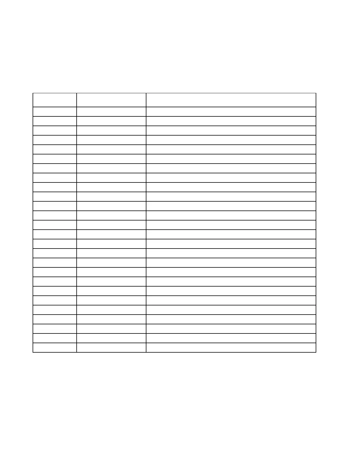
Table 12-1. Controls and indicators, RFL 9780 IF/BF Module
Component
Designator
Name/
Description
Function
J1 Jack Connects voice filter module to IF/BF module
J2 Jack Connects voice filter module to IF/BF module
J3 Jack Test jack for loading and testing XILINX
R10 Potentiometer Sets signal level into 2
nd
mixer
R15 Potentiometer Adjusts frequency of 5.12 mHz crystal oscillator
R28 Potentiometer Sets signal level into 3rd mixer
SW1 DIP switch Sets 1
st
mixer oscillator frequency
SW2 DIP switch Sets 1
st
mixer oscillator frequency
TP1 Test point Ground
TP2 Test point Input to 1
st
mixer
TP3 Test point IF/BF output
TP4 Test point Input to 2
nd
mixer
TP5 Test point Local oscillator for 1
st
mixer
TP6 Test point DC control signal for phase locked loop oscillator
TP7 Test point Unattenuated input to 3
rd
mixer
TP8 Test point Input to 3
rd
mixer
TP9 Test point Output of 3rd mixer
TP10 Test point Ground
TP11 Test point Local oscillator frequency of 3
rd
mixer (6 or 6.25 kHz)
TP12 Test point Output of 1
st
mixer
TP13 Test point Signal input to IF/BF
TP14 Test point Output of 2
nd
mixer
TP15 Test point 26 kHz local oscillator for mixer in voice module
TP16 Test point + 8Vdc
TP17 Test point + 5Vdc
TP18 Test point + 10Vdc