RFL 9780 RFL Electronics Inc.
November 1, 2000 8-1 (973) 334-3100
SECTION 8. TRANSMITTER MODULE
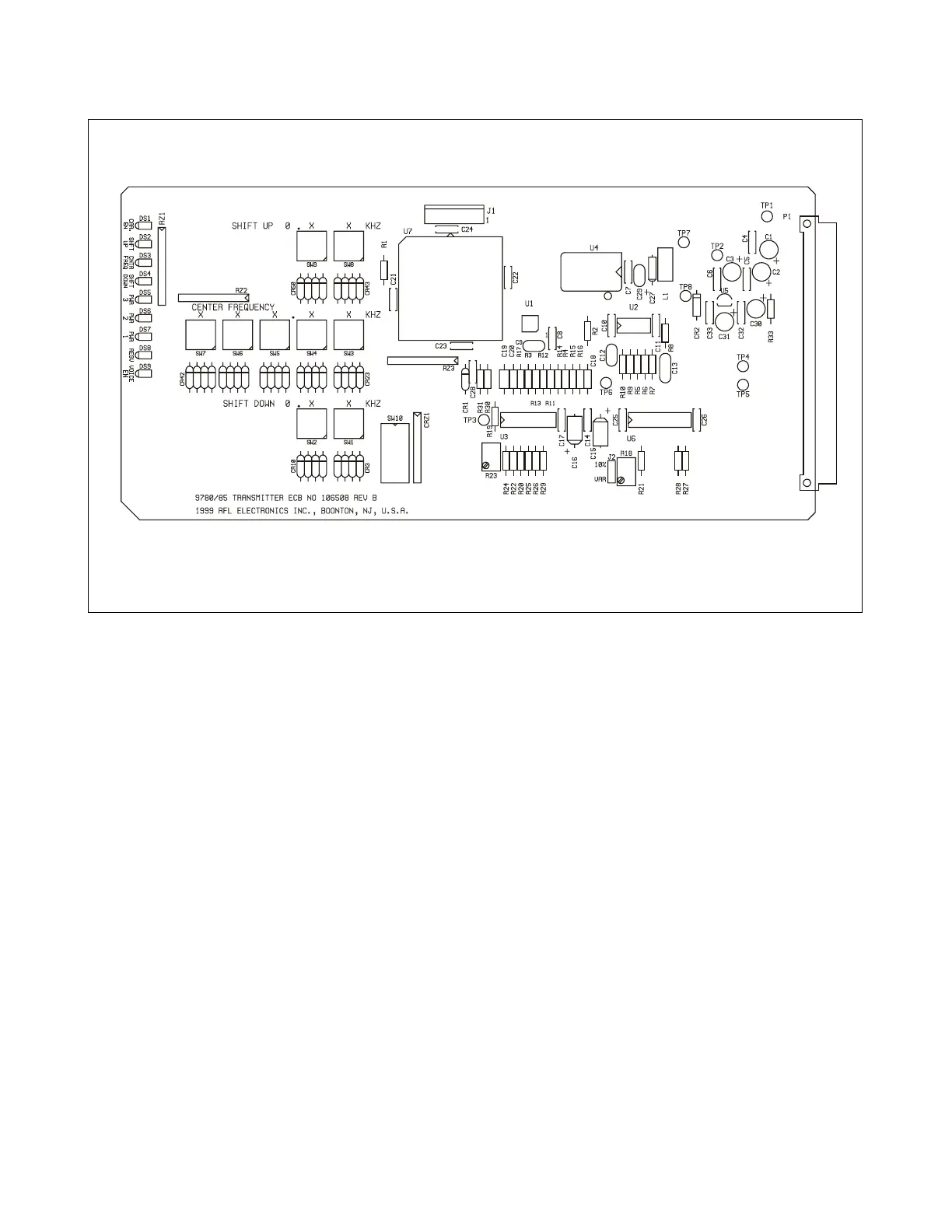
Figure 8-1. RFL 9780 Transmitter Module
8.1 DESCRIPTION
The RFL 9780 Transmitter Module (Figure 8-1) is a programmable powerline carrier transmitter,
utilizing Direct Digital Synthesis (DDS). The basic principle of DDS is to generate a stepped sine wave
from a high speed digital-to-analog (D/A) converter by reading a sine look-up table stored in ROM.
The output of the DDS is fed into an anti-aliasing filter and the signal level is adjusted to achieve the
desired overall transmission power (10W, 3W or 1W output of the power amplifier).
The desired output frequency is selected by programming a set of direct reading rotary switches.
The module has presets for the center frequency, a shift up, and a shift down. External signals also
select the output level of the module corresponding to 10W, 3W or 1W. An additional “Reserve” input
can be used to further reduce transmit power by 10% to 35% of normal. The output of the module can
be totally disabled via an input signal.
Nine LEDs display the module status at all times. They indicate which of the three frequencies are
selected and which output power level is in use. LEDs also indicate if the transmitter carrier, or reserve
is enabled.