RFL 9780 RFL Electronics Inc.
April 8, 2003 12-3 (973) 334-3100
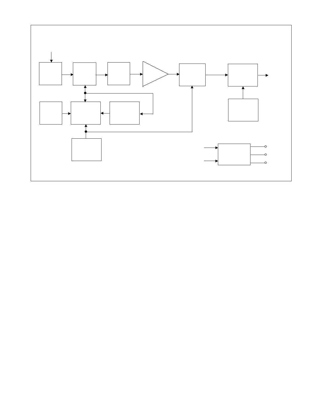
Figure 12-2. Block diagram, RFL 9780 IF/BF Module
a. Crystal Oscillator . Transistor Q1, crystal Y1, varactor CR2, and their associated components form
a crystal oscillator. This oscillator serves as the beat frequency oscillator (BFO) for the product
detector, as well as the frequency reference for the frequency synthesizer. The voltage applied to the
cathode of CR2 determines the output frequency of the crystal oscillator. FREQ ADJ potentiometer
R15 is used to adjust this voltage for an output frequency of 5.12 mHz.
b. Synthesizer. Synthesizer U3 sets the frequency at which the demodulator section will receive inputs.
DIP switches SW1 and SW2 program U3 for a frequency 2 kHz below the incoming carrier frequency.
This frequency difference will produce the 2-kHz if signal. Frequencies are selected by placing sections
of SW1 and SW2 in the OFF position and adding up the frequencies each section represents. See
paragraph 12.4.1 for more information on setting these switches.
The output of the crystal oscillator is fed to U5-15. U5 is a decade counter whose 512-kHz output (U5-
4 and U5-9) is fed to U3-27. U3 divides this signal by 1024, creating a 500-Hz reference frequency.
Because of this reference frequency, the synthesizer can only be programmed for frequencies that are
500 Hz apart. 250-kHz increments are accommodated by changing the frequency of the second local
oscillator. See paragraph 12.3.i for more information.
FREQUENCY
SYNTHESIZER
DIP
SWITCHES
TUNED
VOLTAGE-
CONTROLLED
OSCILLATOR
CRYSTAL
OSCILLATOR
INPUT
LOW-PASS
FILTER
INPUT
MIXER
IF
FILTER
IF
MPLIFIER
PRODUCT
DETECTOR
OUTPUT
MODULATOR
2ND LOCAL
OSCILLATOR
CARRIER
INPUT
SIGNAL
BF OUT
* WHEN PRESENT
ON-BOARD
REGULATORS
+10V
+8V
+5V
+15V
-15V