RFL 9780 RFL Electronics Inc.
September 8, 2001 18-19 (973) 334-3100
18.4.3 CONTROLS AND INDICATORS
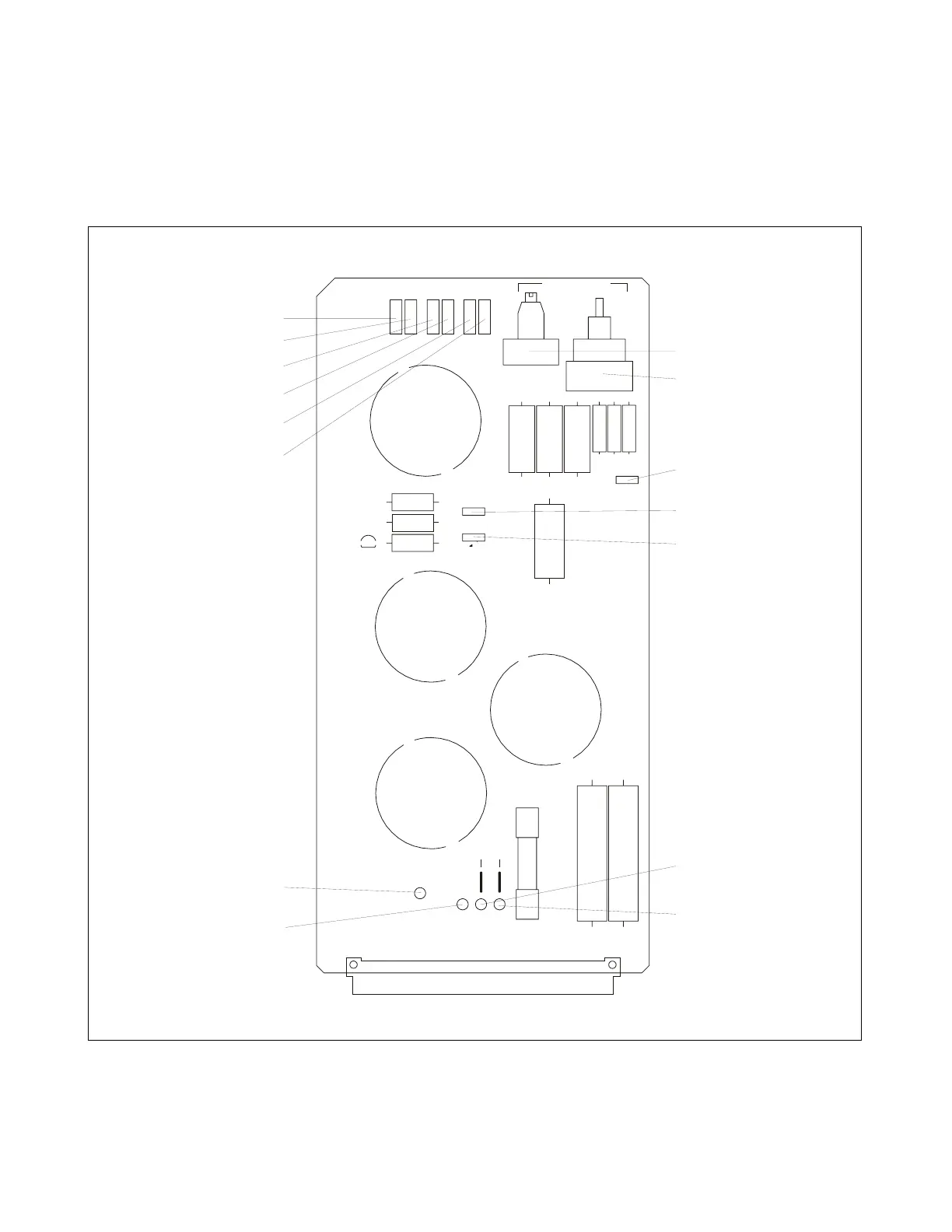
Figure 18-8 shows the location of all controls and indicators on the Dual Hybrid module. These
controls and indicators are described in Table 18-5. Only TP5-10, SW1 and R4 are accessible with the
Dual Hybrid Module installed in the chassis. All others are accessible when the module is removed
from the chassis or is on a card extender.
TP9
P1
L2
TP4
SW1
TP10
J1
R15
R3
CR1
F1
R4
L1
TP3
TP5
TP6
R16
J2
R1
R5
R7
R8
R10
R11
R9
TP2
J3
L3
L4
R2
TP7
TP8
R6
TP1
J4
J5
9780/85 HYBRID ECB NO. 106623 REV-A
DUAL SINGLE
2000 RFL ELECTRONICS INC., BOONTON, NJ, U.S.A.
TX1 RXTX2
IN
OUT
I-LIMIT
TERM
E
C
N
A
L
A
B
COARSE
FINE
HI LOLOLO HIHI
B
A
32
AC
1
1
1
1
1
1
1
1
1
N/A
TP6
TP5
TP10
TP9
TP8
TP7
R4
SW
J3
J1
J2
TP2
TP1
TP3
TP4
Figure 18-8. Controls and indicators, RFL 9780 Dual Hybrid Module