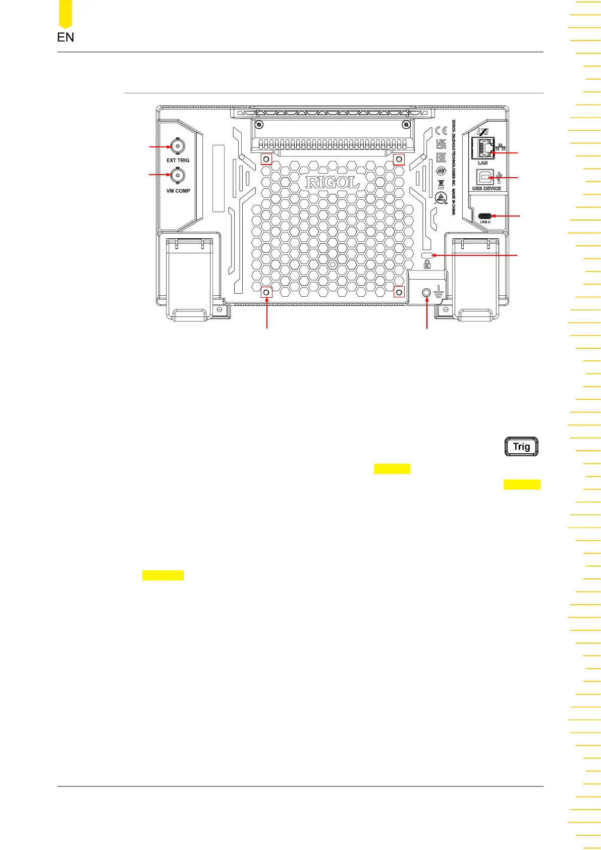
4.4.2 Rear Panel Overview
4
3
6
5
1
2
7
8
Figure 4.6 Rear Panel
1. VM COMP Output Interface
The multimeter outputs a pulse via [VM Comp] connector after each
measurement when VM output is enabled. To enable the VM output, press
on the front panel (you can also click or tap the Trigger label at the bottom of the
screen to enter the trigger setting interface), then click or tap "ON" for the Output
menu to enable the VMC output.
2. External Trigger Input Interface
Triggers the multimeter by connecting a pulse via the [EXT TRIG] connector after
external trigger is selected. To enable the external trigger, click or tap to select
External.
3. LAN Interface
Connects the instrument to network via this interface. The instrument is in
compliance with the standards specified in
LXI Device Specification 2011
. It can be
used to set up a test system with other standard devices. Then you can use the
Web Control to send the SCPI commands to control the instrument.
4. USB DEVICE Interface
Connects the instrument to the PC via this interface. Then you can use the PC
software to send the SCPI commands or use the user-defined programming to
control the instrument.
5. USB Type-C Power Interface
Quick Start
Copyright ©RIGOL TECHNOLOGIES CO., LTD. All rights reserved. DM858 Series User Guide
19