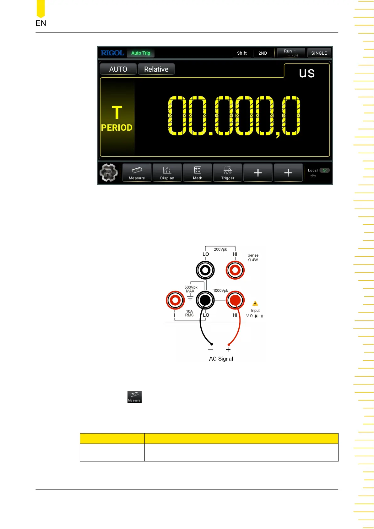
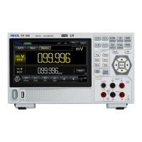
Figure 5.23 Period Measurement Interface
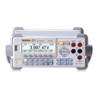
2. Connect red lead to terminal Input HI and black lead to terminal Input LO, as
shown in the figure below.
Figure 5.24 Period Measurement Connection Diagram
3. Click or tap to set the range of the period measurement.
Table 5.11 Period Measurement Parameter Setting
Parameter Description
Range Auto, 100 mV, 1 V, 10V, 100 V, 750V
Front Panel Operation
Copyright ©RIGOL TECHNOLOGIES CO., LTD. All rights reserved. DM858 Series User Guide
55