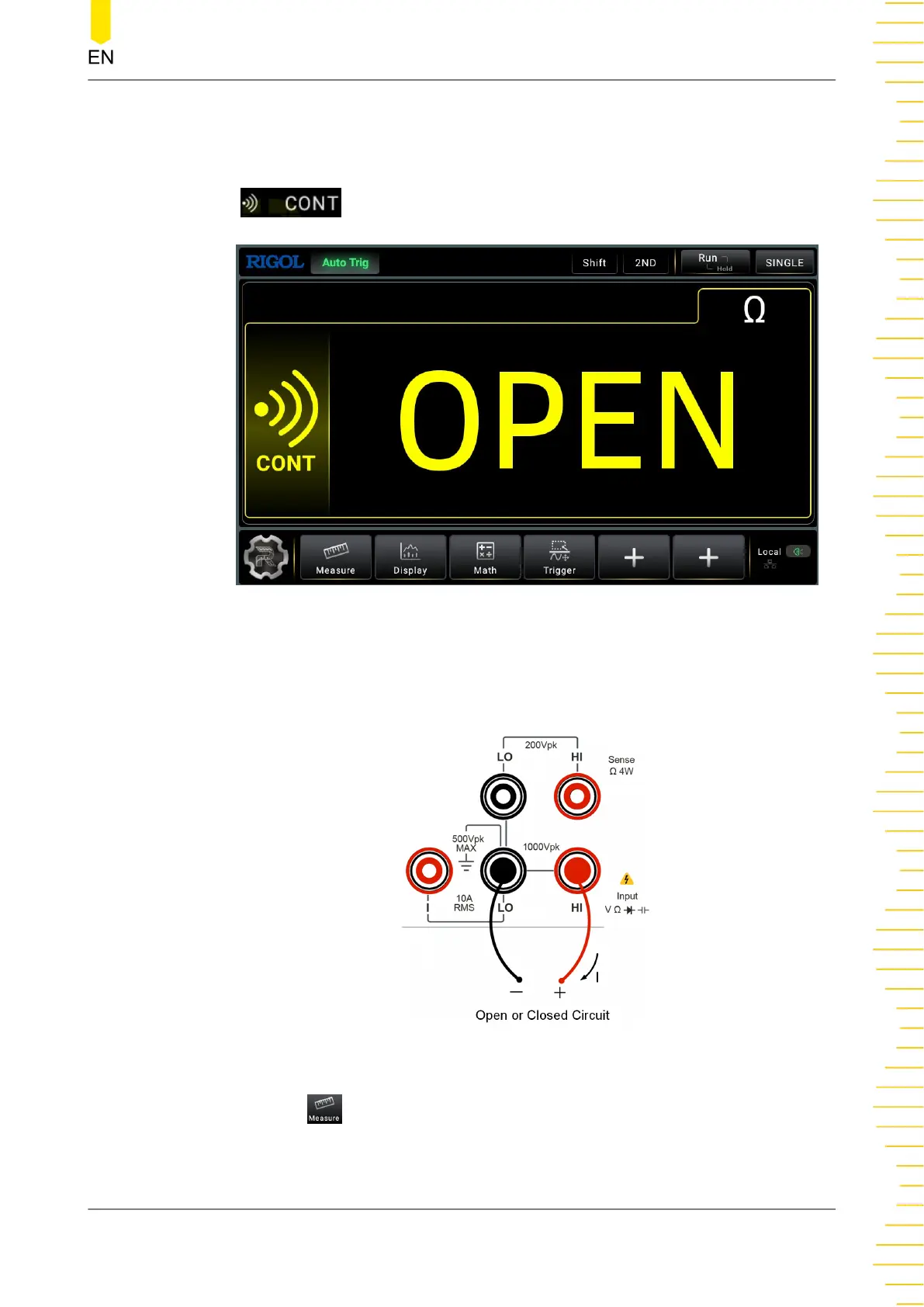
- Click or tap the main measurement item shown at the left part of the main
display area. The measurement items are displayed. Click or tap to select
to enter the continuity measurement interface.
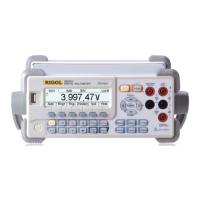
Figure 5.17 Continuity Test Interface
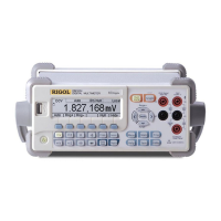
2. Connect red lead to terminal Input-HI and black lead to terminal Input-LO, as
shown in the figure below.
Figure 5.18 Continuity Test Connection Diagram
3. Click or tap
to set the short-circuit resistance. By default, the short-circuit
resistance is 10 Ω. The value is set before leaving factory and you can directly
Front Panel Operation
Copyright ©RIGOL TECHNOLOGIES CO., LTD. All rights reserved. DM858 Series User Guide
49